Eureka AIR delivers breakthrough ideas for toughest innovation challenges, trusted by R&D personnel around the world.

Cross-dispersed spectrometer in a spectral domain optical coherence tomography system

a technology spectrometer, which is applied in the field of optical coherence tomography to achieve the effects of high dispersion, more pixels, and higher dispersion

Inactive Publication Date: 2006-07-27
CARL ZEISS MEDITEC INC
View PDF18 Cites 163 Cited by
  • Summary
  • Abstract
  • Description
  • Claims
  • Application Information

AI Technical Summary

Benefits of technology

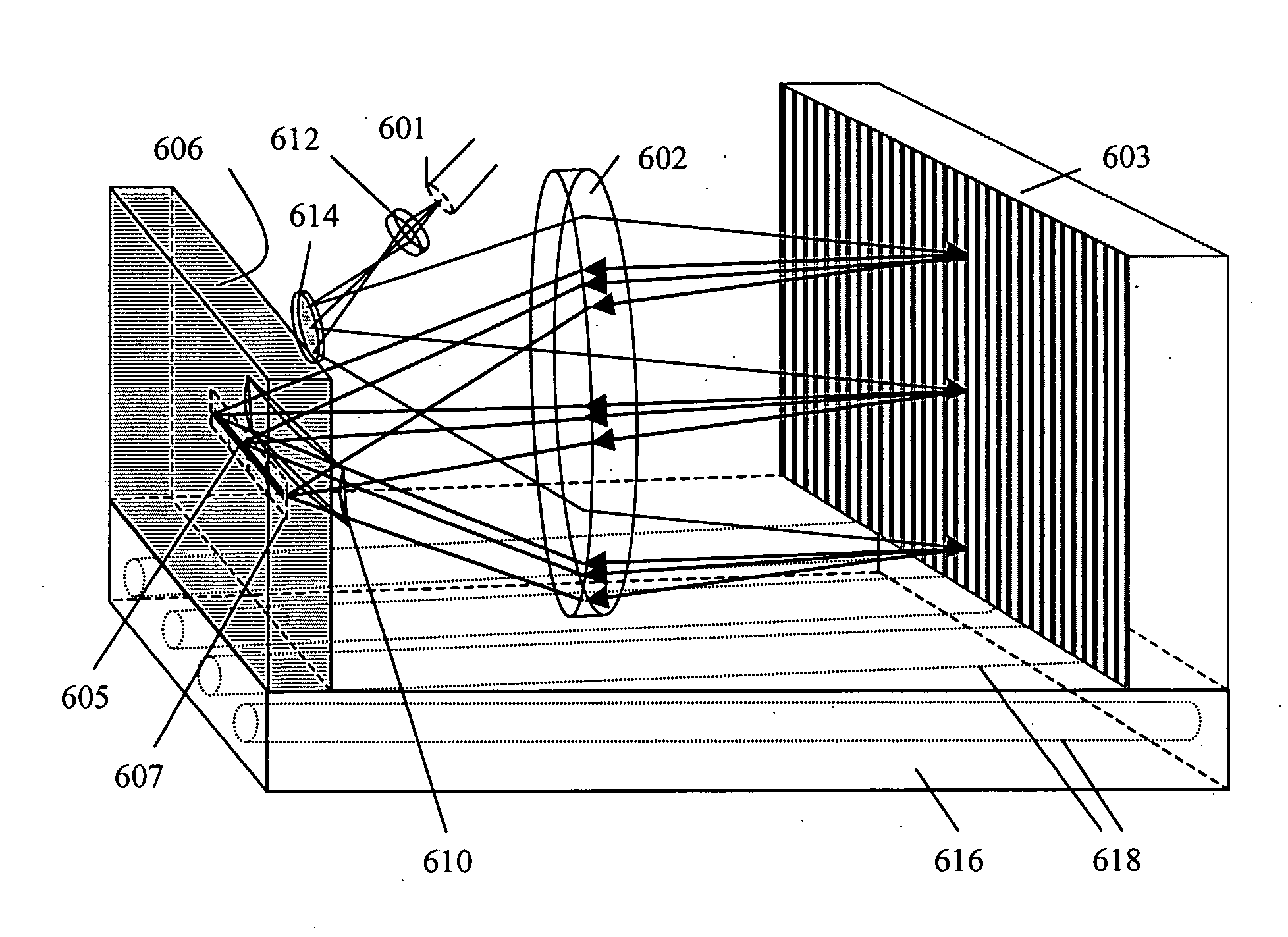
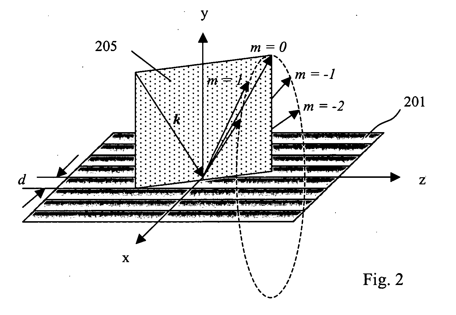
The present invention is about a new design for high-resolution spectrometers that can be used in a cross-dispersed echelle or echelon configuration for SD-OCT systems. The spectrometer includes a first grating for dispersing the incoming light beam as a function of wavelength, followed by a second dispersive element that can be a grating or prism, with its dispersion direction oriented perpendicular to the first grating. A linear detector array receives and measures the diffracted, dispersed light of interest. The spectrometer is designed to provide higher dispersion on the detector array, which increases the resolution of the spectrometer and allows for better depth range and better balanced or phase-sensitive detection. It can use compact and low-cost sensors and can be easily integrated into a compact and affordable OCT scanner.

Problems solved by technology

Such arrays are not commonly available and even if such an array would be made available, the optics layout would necessarily be very large even in a Littrow arrangement, causing thermal problems for example.

Method used


Image

  • Cross-dispersed spectrometer in a spectral domain optical coherence tomography system
  • Cross-dispersed spectrometer in a spectral domain optical coherence tomography system
  • Cross-dispersed spectrometer in a spectral domain optical coherence tomography system

Examples


Embodiment Construction

[0041] As is well known to those skilled in the art, a broad band light beam can be dispersed into its spectral components in a number of ways, including the use of a prism, a grating, an arrayed waveguide grating or a combination of optical filters. A grating is generally used in most spectrometers because of its high resolving power and hence high spectral resolution within a limited space. In many applications, a plane grating is preferred because of its low cost as compared to other more complex gratings such as a curved grating, a volume holographic grating, or a photonic crystal grating.

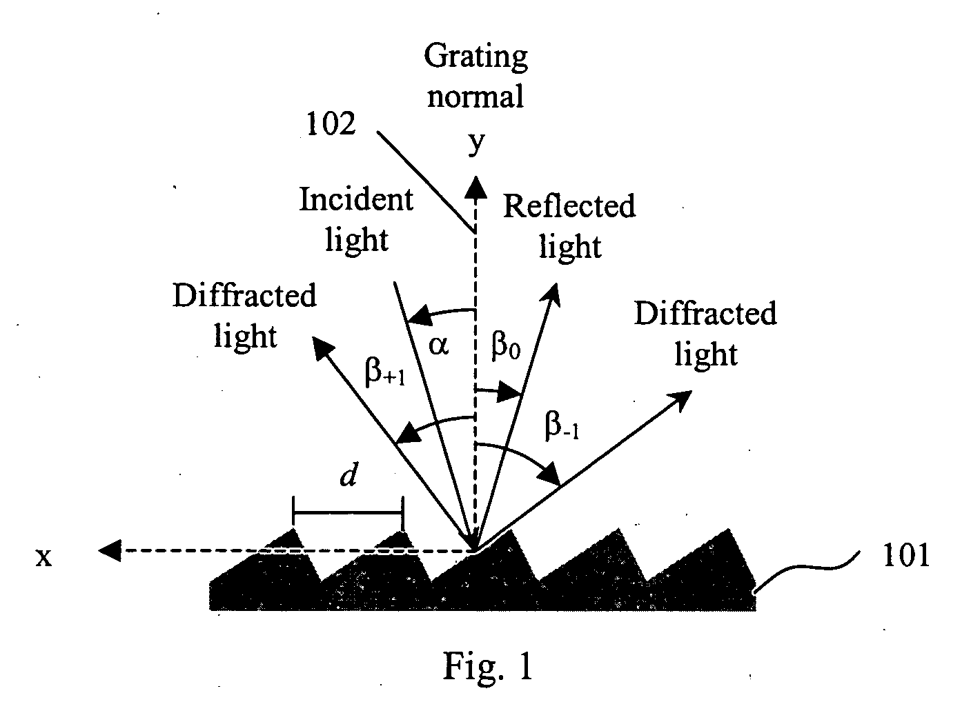
[0042]FIG. 1 shows the case of a plane reflection grating 101, the grating equation is given by

mλ=d(sin α+sin βm)   (1)

where m is the diffraction order which is an integer, λ is the wavelength of light, d is the grating period, α is the angle of incidence, and βm is the angle of diffraction. The angle of incidence and angle of diffraction are measured from the grating normal 102, i.e. the d...


PUM


Abstract

A spectral-domain optical coherence tomography system using a cross-dispersed spectrometer is disclosed. The interfered optical signal is dispersed by a grating into several orders of diffraction, and these orders of diffraction are separated by an additional dispersive optical element. The spectral interferogram is recorded by a set of linear detector arrays, or by a two-dimensional detector array.

Description

PRIORITY [0001] This application is a continuation-in-part of U.S. patent application Ser. No. 11 / 196,043, filed on Aug. 3, 2005. [0002] This application claims the benefit of the filing date under 35 U.S.C. § 119(e) of U.S. Provisional Patent Application Ser. No. 60 / 645,662, filed Jan. 21, 2005.BACKGROUND OF THE INVENTION [0003] 1. Field of the Invention [0004] The invention relates generally to optical coherence tomography, specifically to the use of a cross-dispersed, echelle configuration, spectrometer in a spectral domain optical coherence tomography system. [0005] 2. Description of Related Art [0006] Optical Coherence Tomography (OCT) is a technology for performing high-resolution cross sectional imaging that can provide images of tissue structure on the micron scale in situ and in real time. In recent years, it has been demonstrated that spectral domain OCT has significant advantages in speed as compared to time domain OCT. In spectral domain OCT (SD-OCT) the optical path len...

Claims


Application Information

Patent Timeline
Patent Type & Authority Applications(United States)
IPC IPC(8): G01J3/28
CPCG01J3/02G01J3/0208G01J3/0224G01J3/0256G01J3/14G01J3/18G01J3/1809G01J3/2803G01N21/4795
Inventor HORN, JOCHEN M. M.O'HARA, KEITH E.
Owner CARL ZEISS MEDITEC INC
Why Eureka
Eureka Blog
Learn More