Spatially corrected full-cubed hyperspectral imager

Active Publication Date: 2007-07-10
SURFACE OPTICS
View PDF12 Cites 164 Cited by
  • Summary
  • Abstract
  • Description
  • Claims
  • Application Information

AI Technical Summary

Benefits of technology

[0011]A spatially corrected hyperspectral imager according to the present invention achieves accurate spectral and spatial resolution by using a micro-lens array (MLA) as a series of field lenses, with each lens distributing a point in the image scene received through an objective lens across an ar

Problems solved by technology

Scanning hyperspectral imagers are complex and large.
Mathematical operations performed by image processing cannot reconstruct information lost as a result of the Bayer filter design.
However, this loss of data can affect a variety of applications including those where a direct sp

Method used


Image

  • Spatially corrected full-cubed hyperspectral imager
  • Spatially corrected full-cubed hyperspectral imager
  • Spatially corrected full-cubed hyperspectral imager

Examples


Embodiment Construction

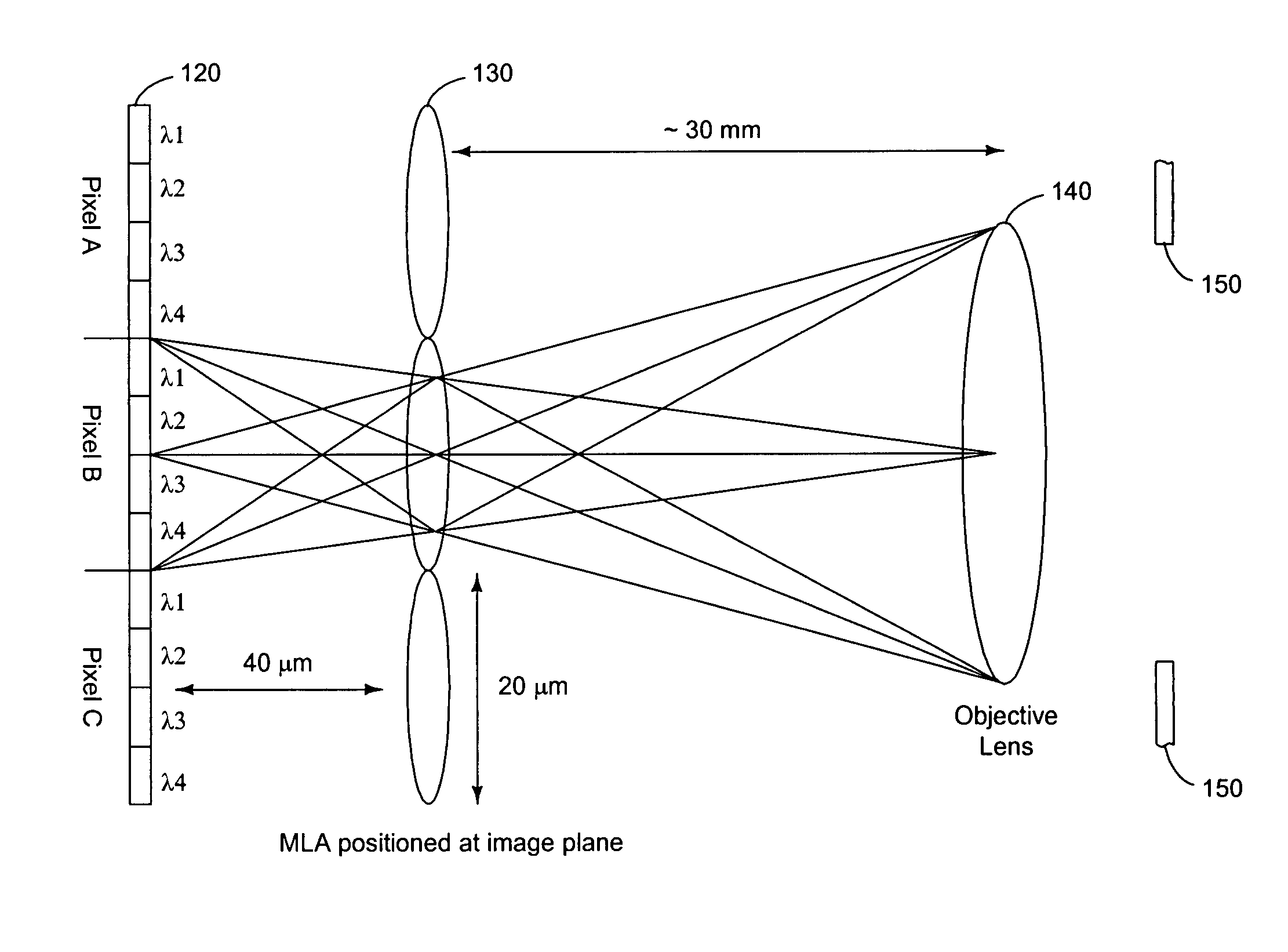
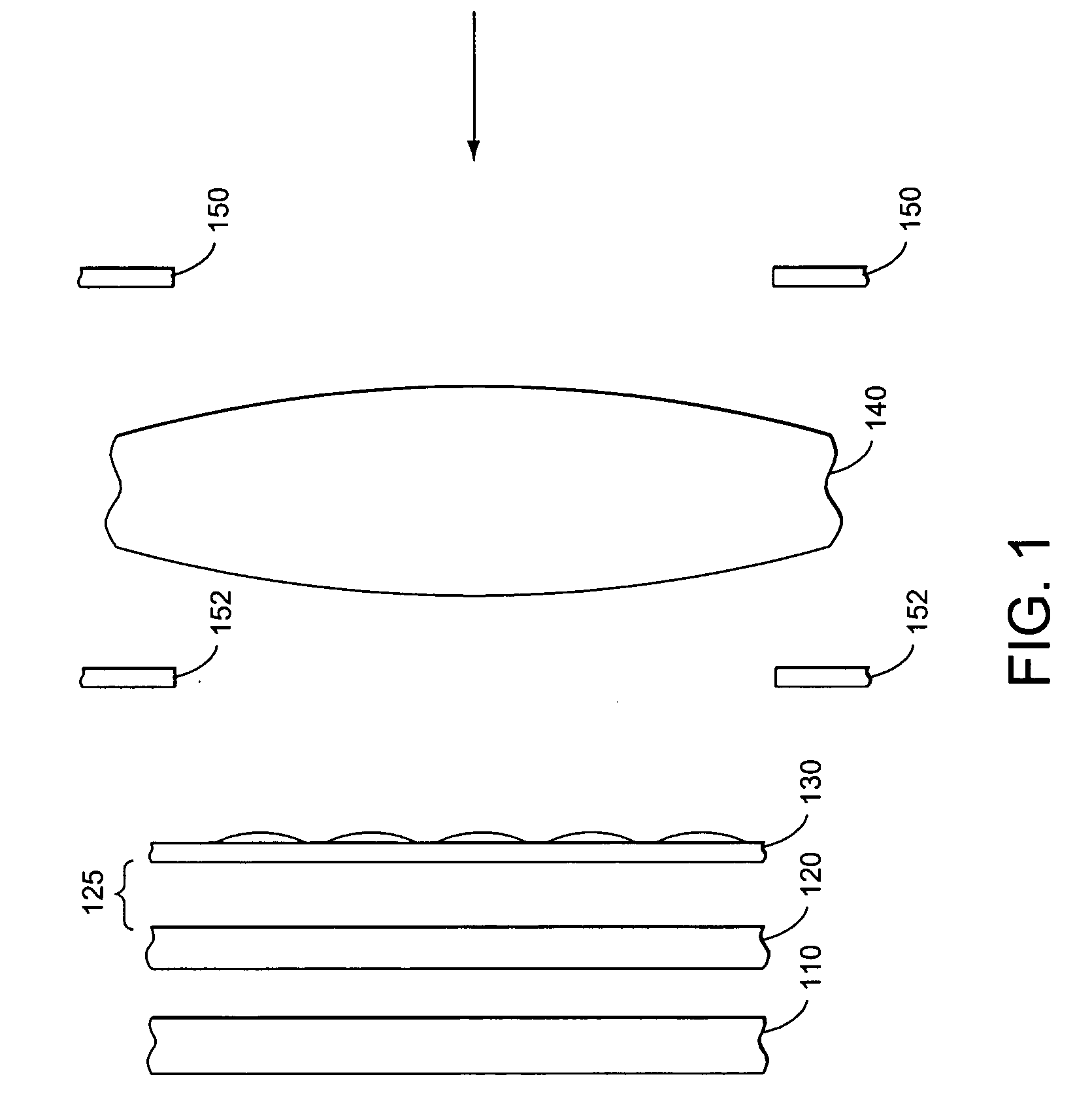
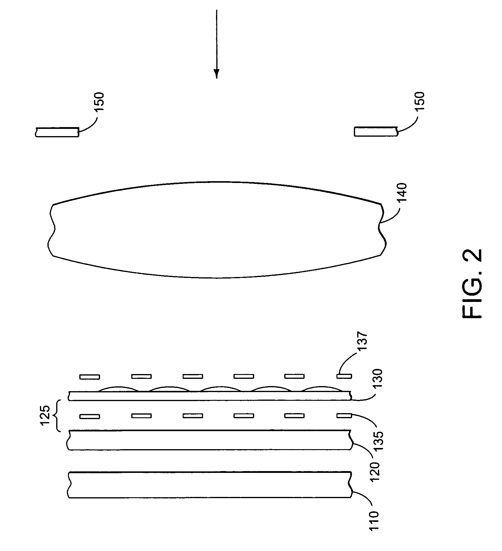
[0028]FIG. 1 shows the side view of the layers of the hyperspectral imager according to the present invention. Detector array 110, color filter array 120, and micro-lens array (MLA) 130, each shown separated for clarity, are rigidly attached to each other. MLA 130 is positioned where objective lens 140 forms an image of the object under observation. Detector 110 is placed where the lenses in MLA 130 form an image of the exit pupil of objective lens 140. Color filter array 120 should be placed as close as feasible to detector 110 to ensure minimal spectral crosstalk and maximum efficiency. Optional spacing 125 can be filled with glass, other optically transparent material, vacuum, or air. Each lens of MLA 130 distributes light across a super pixel area of filter array 120 and detector array 110.

[0029]Objective lens 140 is preferably a telecentric lens. The chief ray for each field point of the image formed by a telecentric lens is perpendicular to the image plane. The chief ray is th...


PUM


Abstract

A hyperspectral imager that achieves accurate spectral and spatial resolution by using a micro-lens array as a series of field lenses, with each lens distributing a point in the image scene received through an objective lens across an area of a detector array forming a hyperspectral detector super-pixel. Each sub-pixel within a super-pixel has a bandpass or other type filter to pass a different band of the image spectrum. The micro-lens spatially corrects the focused image point to project the same image scene point onto all sub-pixels within a super-pixel. A color separator can be used to split the image into sub-bands, with each sub-band image projected onto a different spatially corrected detector array. A shaped limiting aperture can be used to isolate the image scene point within each super-pixels and minimize energy coupling to adjacent super-pixels.

Description

RELATED APPLICATIONS[0001]This application claims the benefit of U.S. provisional patent application 60 / 527,252 filed Dec. 5, 2003 entitled “Spatially corrected full-cubed Hyperspectral imager”, incorporated herein by reference.BACKGROUND[0002]1. Field of the Invention[0003]The invention relates generally to spectrometry and particularly to hyperspectral imaging.[0004]2. Prior Art[0005]Hyperspectral imagers (HSI) are a class of spectrometers that record energy in many discrete spectral bands or colors simultaneously at a multitude of spatial picture elements, called pixels. Standard broadband imagers record one value at each picture element for all the detected incident energy across a wide spectrum. Hyperspectral imagers differ from standard broadband imagers by creating an additional spectral dimension in addition to the two spatial dimensions created from a two-dimensional array of detectors. Each HSI picture element may have ten to hundreds of wavelength values recorded.[0006]So...

Claims


Application Information

Patent Timeline
IPC IPC(8): G01N21/25
CPCG01J3/02G01J3/0208G01J3/2803G01J3/2823G01J3/36G01N21/25
Inventor DOMBROWSKI, MARKCATANZARO, BRIAN
Owner SURFACE OPTICS
Why Eureka
Try Eureka