

Method of determining a three-dimensional velocity field in a volume
volume technology, applied in the field of determining a three-dimensional velocity field in a volume, can solve the problem that the intensity of a voxel is not sufficient to determine the three-dimensional velocity field, and achieve the effect of reconstructing the voxel intensities
Active Publication Date: 2005-03-24
LAVISION
View PDF12 Cites 11 Cited by
- Summary
- Abstract
- Description
- Claims
- Application Information
AI Technical Summary
Benefits of technology
There is more specifically provided that the grid selected for the interrogation volumes be equal or finer than the equivalent pixel size of the cameras so that several voxels of an observation plane normal to the camera equal the size of one pixel xn, yn and that the intensity of the voxels be calculated from a subpixel accurate interpolation of the intensities of the camera image points xn, yn of the cameras. This means that the voxels are to be smaller than the pixels of a camera so that it is made possible to more accurately determine the intensity of the voxels.
In an advantageous variant, the observation volume is illuminated e.g., in thin layers, less illuminated voxels then lying along a line of sight so that reconstruction of the voxel intensities is rendered more stable and more accurate while it is still possible to determine a velocity field with a great three-dimensional depth on the other side.
Problems solved by technology
Determining the intensity of a voxel is not yet sufficient to determine the three-dimensional velocity field.
Method used
View moreImage
Smart ImageViewing Examples

Examples
Embodiment Construction
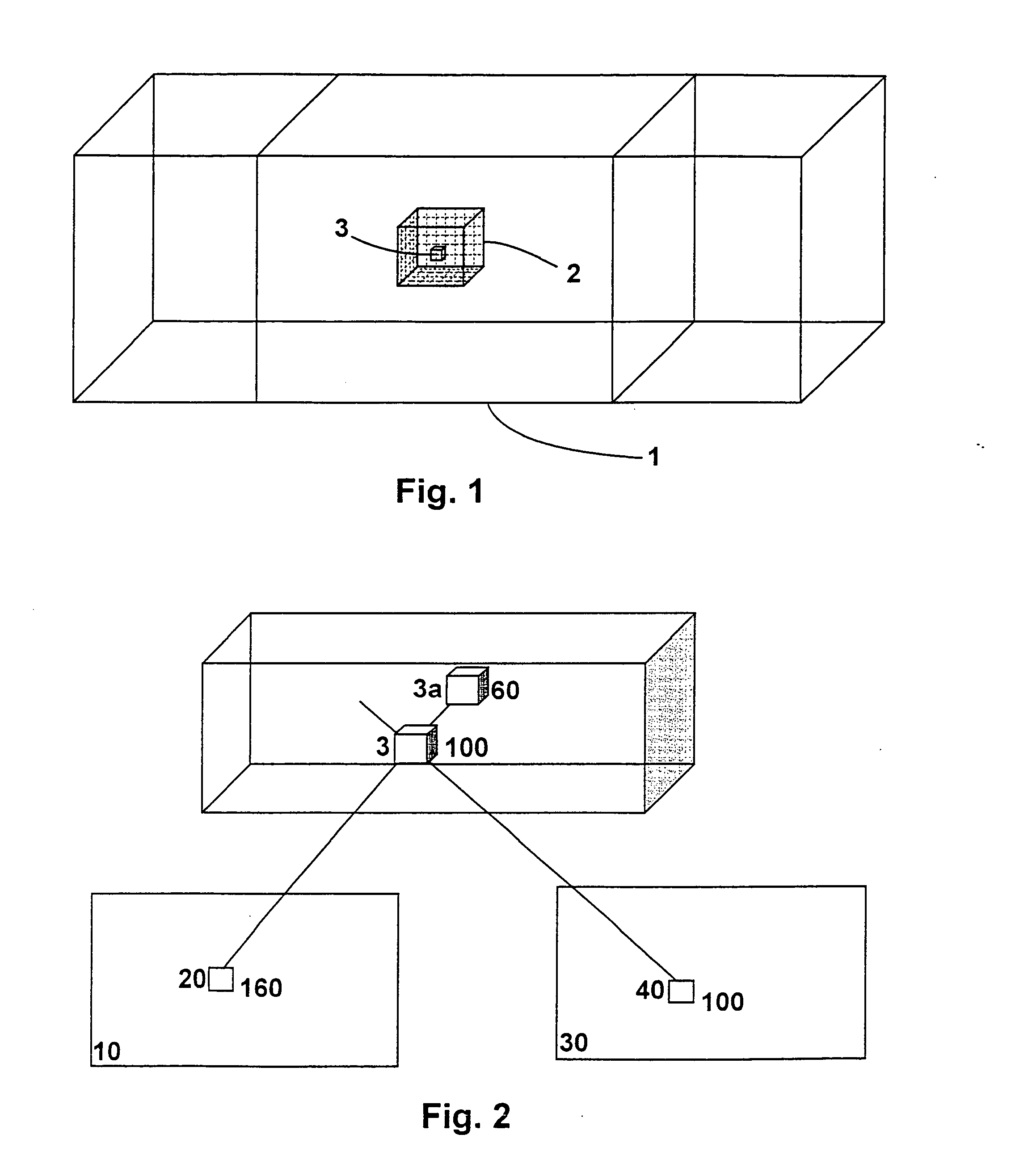
In the camera image of camera 10, the pixel 20 receives light from the volume elements (voxels) 3 and 2a at an overall intensity of 160 counts. In the camera image of camera 30, the pixel 40 receives light from volume element 3 only at an intensity of 100 counts. Upon reconstructing the voxel 3, the minimum intensities of the pixels 20 and 40 yield the right voxel intensity of 100 counts.
Login to View More PUM
 Abstract
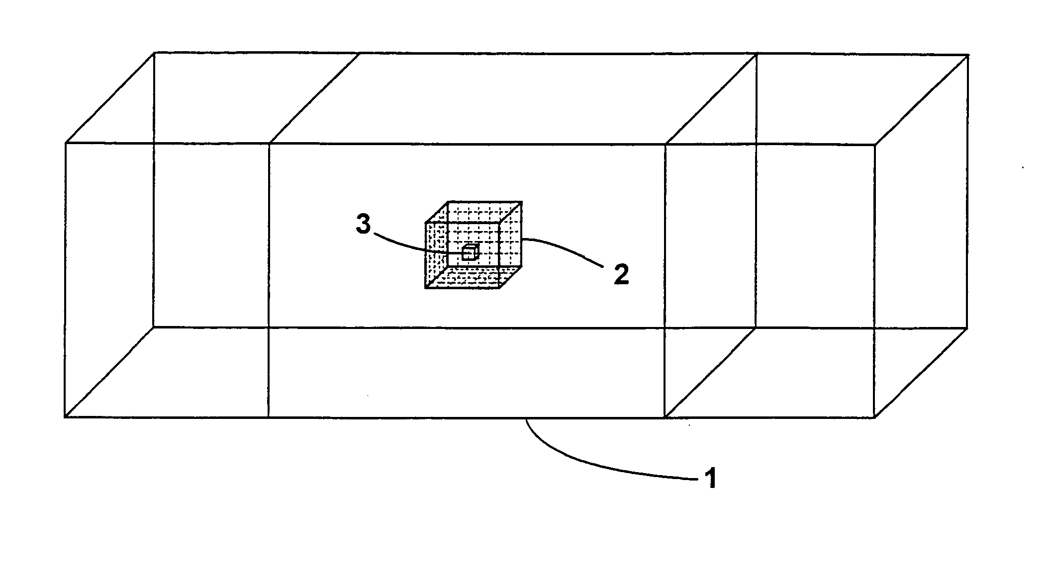
A method of determining a three-dimensional velocity field in a volume, the particles within the volume being excited to radiate by illuminating said volume, a) at least two cameras simultaneously image capturing the observation volume at two different instants of time (t1, t2) at least, b) the observation volume being divided into small volume elements (voxels), c) each voxel being projected at the location x, y, z onto the image points (xn, yn) of the at least two cameras using a projection equation, d) the intensity of all the voxels being reconstructed from the measured intensity of the respective ones of the associated image points (xn, yn), e) a plurality of voxels being combined to form an interrogation volume, f) the displacement vector (dx, dy, dz) being determined at the times (t1, t2) at the same location by a three-dimensional cross correlation of the two interrogation volumes.
Description
FIELD OF THE INVENTION The invention relates to a method of determining a three-dimensional velocity field in a volume. DESCRIPTION OF THE PRIOR ART A standard method of measuring gas or liquid velocities consists in the Particle Image Velocimetry (PIV) method (DE 199 28 698 A1) by which the flow is seeded with small particles and a thin observation plane is usually illuminated twice in fast sequence by means of a laser and is image captured by a camera positioned normal to the observation plane, said camera being capable of taking a fast sequence of two images. These camera images are divided into small interrogation windows, said two interrogation windows being cross correlated at a location x, y with the two instants of time at which the image was captured in order to determine, through the highest correlation peak, the most probable (dx, dy)-displacement vector between the two interrogation windows. (dx, dy) thereby are the two displacement vector components normal to the obse...
Claims
Login to View More Application Information
Patent Timeline
 Patent Type & AuthorityApplications(United States)
IPC IPC(8): G01P5/00G01P5/20G01P5/22G06T7/20
CPCG01P5/001G06T7/2086G01P5/22G06T7/285
InventorWIENEKE, BERNHARD
OwnerLAVISION