
Disk array device, method of extending storage capacity and computer program

a technology of disk array device and storage capacity, which is applied in the direction of digital storage, redundant data error correction, instruments, etc., can solve the problems of increasing the possibility of producing a faulty disk device, raising processing overhead, and inability to maintain initial configuration of raids

Active Publication Date: 2005-03-24
NEC CORP
View PDF10 Cites 44 Cited by
  • Summary
  • Abstract
  • Description
  • Claims
  • Application Information

AI Technical Summary

Benefits of technology

The present invention provides a disk array device and method for extending the storage capacity of the device without reducing the data protection capability. The device can add a disk by dividing it into partitions and selecting a partition of the original disk device as the origin of copying. The device can also prepare a new redundancy group by excluding the original redundancy group and adding the new partition to the original redundancy group. The technical effects of the invention include extending the storage capacity of the disk array by adding a new disk without reducing the data protection capability and preparing a new redundancy group to incorporate the new disk.

Problems solved by technology

This is because the probability of producing a faulty disk device increases as the number of disk devices that constitute a redundancy group increases.
Additionally, as the value of i increases, the number of disk devices that are to be accessed in parallel during a degenerative operation increases to raise the processing overhead.
However, there arises a problem that the initial configuration of RAID cannot be maintained when the storage capacity of a disk array is extended by means any of the known techniques.
Additionally, with the known technique (3), the parities are not distributed among all the disks at the time of adding a disk device so that a perfect RAID5 configuration is not realized to consequently reduce the data protection capability of the disk array.

Method used


Image

  • Disk array device, method of extending storage capacity and computer program
  • Disk array device, method of extending storage capacity and computer program
  • Disk array device, method of extending storage capacity and computer program

Examples


1st embodiment

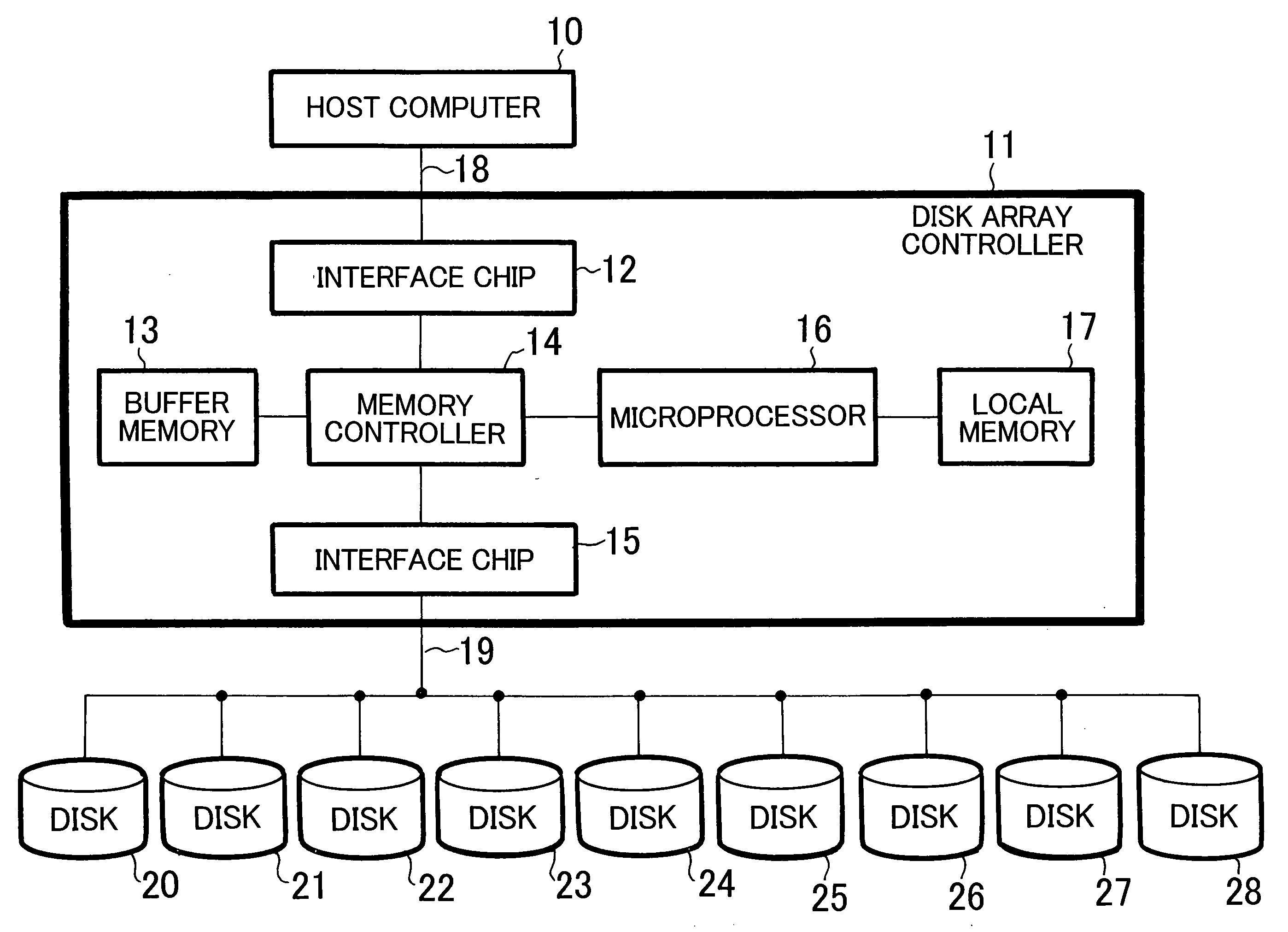
[0069] Referring to FIG. 1, the first embodiment of disk array device according to the invention is a disk array device of a predetermined RAID type comprising a disk array controller 11 connected to a host computer 10 by way of a general purpose bus 18 such as a fiber channel and a plurality of disk devices 20 through 28 connected to the disk array controller 11 also by way of a general purpose bus 19 such as a fiber channel and adapted to use the plurality of disk devices 20 through 28. Note that all the disk devices 20 through 28 have a same storage capacity.

[0070] The disk array controller 11 typically has a hardware configuration as illustrated in the corresponding block of FIG. 1. Interface chip 12 is an interface for connecting the disk array controller 11 to the host computer 10 by way of the general purpose bus 18 and interface chip 15 is an interface for connecting the disk array controller 11 to the plurality of disk devices 20 through 28 by way of the general purpose bu...

example 1 of 1st embodiment

[0099] Referring now to FIG. 9, in the disk array device of the first embodiment in Example 1, the disk array controller 11 includes an IO processing section 30, a read position browsing section 31, a write position browsing section 32, an exclusive control section 33, a redundancy group defining section 34, a copying processing section 35, a copying position browsing section 36, a disk control section 37, a buffer managing section 38, a configuration managing section 39 and a control table 40. The control table 40 is typically generated in a local memory 17 as shown in FIG. 1 and the functional means 30 through 39 can be realized by using a microprocessor 16 and a program stored in the ROM contained in the microprocessor 16 or the local memory 17. More specifically, the program stored in the ROM or the local memory 17 is read by the microprocessor 16 and the function means 30 through 39 are realized on the microprocessor 16 by controlling the operation of the microprocessor 16.

[01...


PUM


Abstract

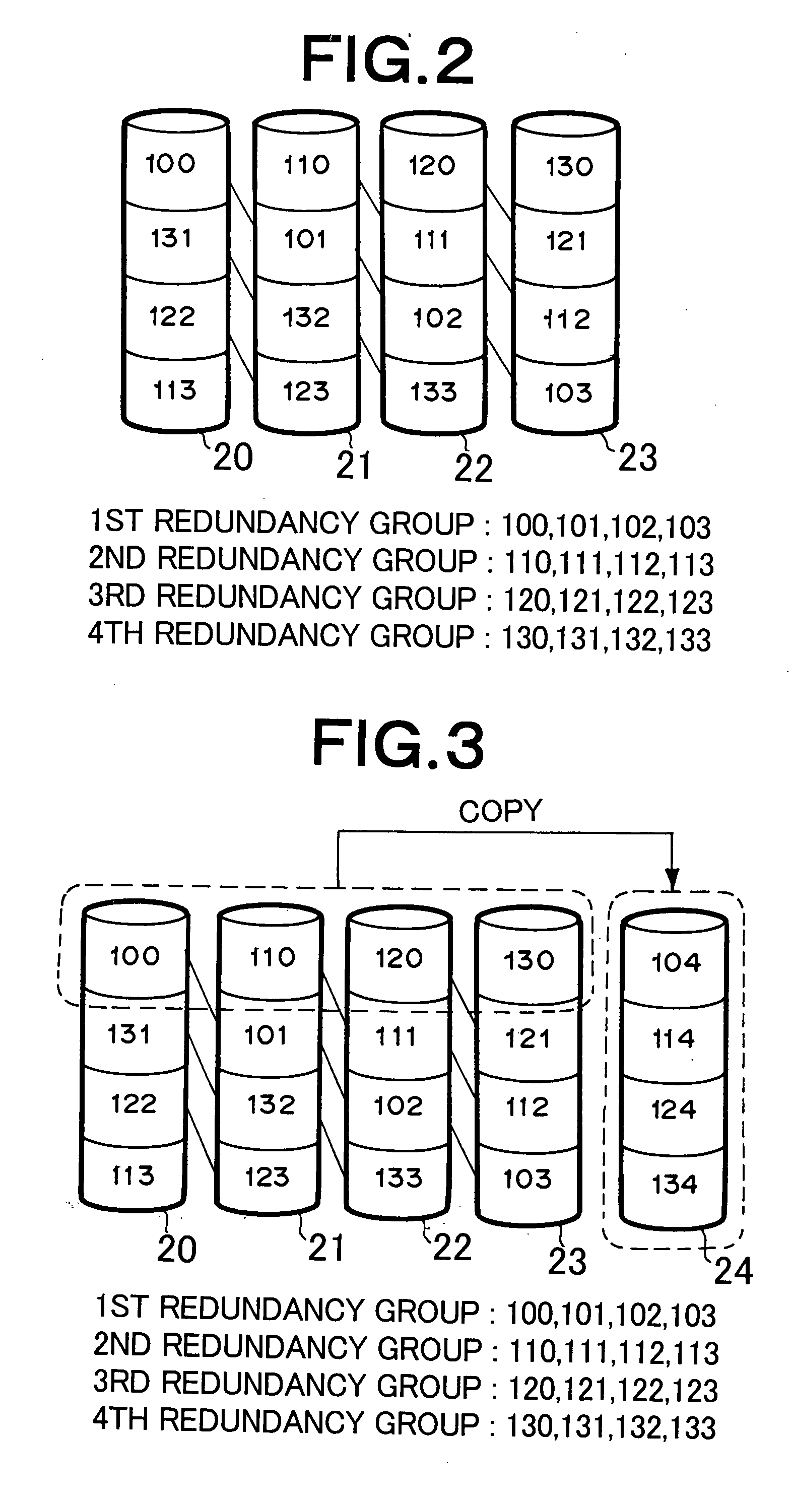
If a disk array device according to the invention initially has four disk devices, which is the smallest number of disk devices for RAID5 (3D+P), the storage region of each of the four disk devices is equally divided by four to produce partitions. Then, four partitions are selected respectively from the four disk devices and combined to form a redundancy group so that a total of four redundancy groups are formed. When another disk device is added, its storage region is also equally divided by four. Four partitions are selected from the four redundancy groups, one from each of the disk devices, and the data of the selected four partitions are copied to the four partitions of the added disk device. After the completion of the copying, the origin of copying partitions are excluded from the original redundancy groups and the corresponding four destination of copying partitions are incorporated to replace the excluded partitions. The four origin of copying partitions excluded from the original redundancy groups are combined to generate a new redundancy group.

Description

BACKGROUND OF THE INVENTION [0001] 1. Field of the Invention [0002] This invention relates to a disk array device and a method of extending the storage capacity of the disk array device. More particularly, it relates to a disk array device adapted to extend the storage capacity thereof by adding disks, while maintaining the RAID type of the disk array and a method of extending the storage capacity of such a disk array device. [0003] 2. Related Background Art [0004] A disk array is an arrangement of a plurality of disk devices in order to enhance the performance and the reliability of a disk system and, at the same time, realize a large storage capacity at reduced cost. Six categories of RAID (redundant array of inexpensive disks) 1 through 6 are known, although each of them have advantages and disadvantages so that they are selectively used depending on applications. For instance, RAID5 is designed to distribute parities to a plurality of disks on a stripe by stripe basis in order t...

Claims


Application Information

Patent Timeline
Patent Type & Authority Applications(United States)
IPC IPC(8): G06F3/06G06F11/10G11C11/00
CPCG06F11/1096G06F3/0604
Inventor SHIRAISHI, KAZUYAKOIKE, HIROHIKO
Owner NEC CORP
Learn More