Stepped manifold array of microchannel heat sinks

a microchannel heat sink and manifold array technology, which is applied in the direction of lasers, laser cooling arrangements, laser details, etc., can solve the problems of reducing the effective life of the heat sink, not being as efficient, and mounting a laser bar at the end of the microchannel heat sink, so as to reduce the corrosion of the fluid path

Active Publication Date: 2005-03-24
II VI DELAWARE INC
View PDF9 Cites 45 Cited by
  • Summary
  • Abstract
  • Description
  • Claims
  • Application Information

AI Technical Summary

Benefits of technology

In accordance with the principles of the present invention, a stair case array of copper microchannel heat sinks is made possible by the use of an insulating manifold that provides a fluid path between adjoining heat sinks that reduces corrosion of the fluid paths in the heat sinks. The manifold has a series of parallel, offset planes or steps each of which provides a fluid connection to a respective microchannel heat sink each of which advantageously may be of the

Problems solved by technology

Unfortunately, mounting a laser bar at the end of a microchannel heat sink, as shown in FIG. 2 of the '043 patent, is not as efficient from the standpoint of maximum heat transfer as mounting the laser bar at the top edge of the heat sink.
Furthermore, vertically stacked arrays of serially-connected microchan

Method used


Image

  • Stepped manifold array of microchannel heat sinks
  • Stepped manifold array of microchannel heat sinks
  • Stepped manifold array of microchannel heat sinks

Examples


Embodiment Construction

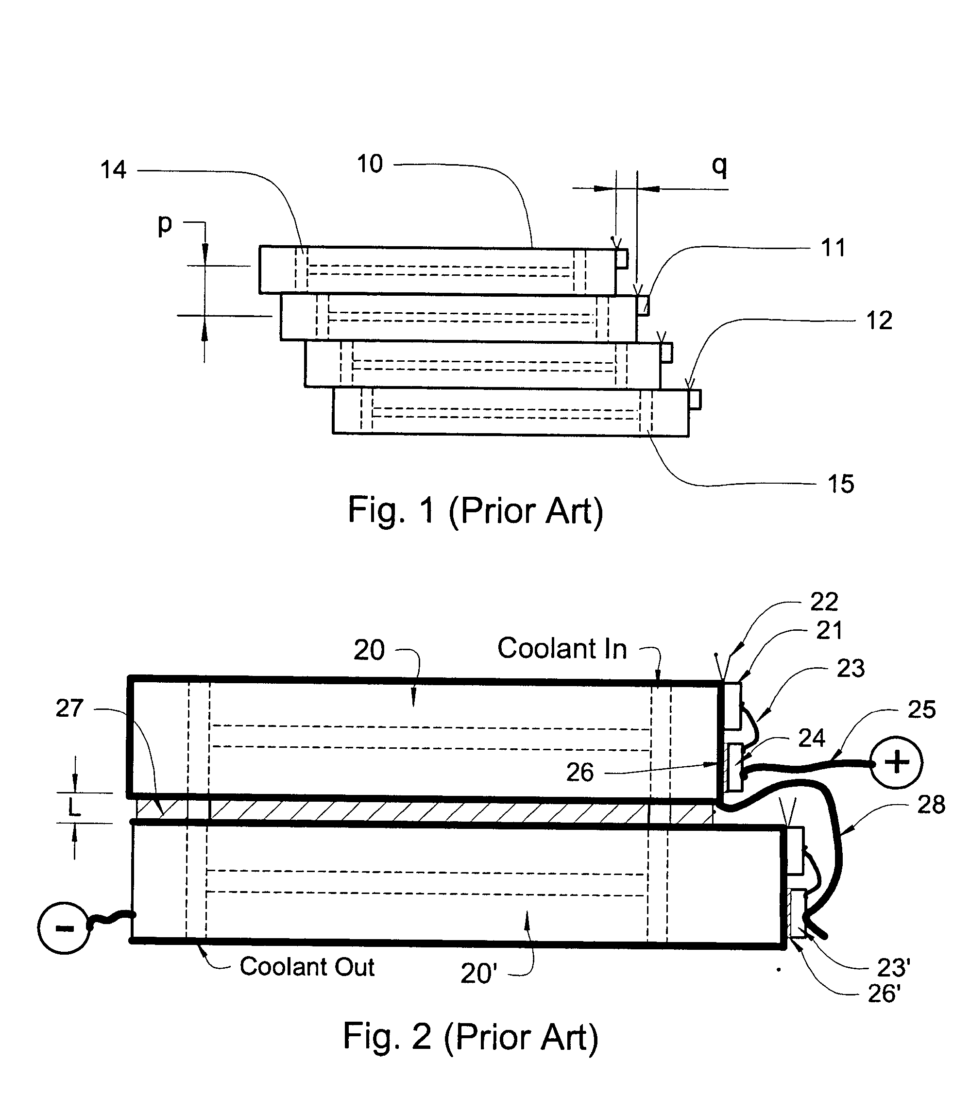
FIG. 1 shows a vertical stack of microchannel heat sinks 10 each having an end-mounted laser bar 15 according to the '043 patent. End-mounting of the laser diode bars 10 allows the distance q between adjacent emitted light beams 16 to be smaller than the distance p between the center lines of adjacent heat sinks whereas mounting the laser diode bars on the top surface of each of the heat sinks determines that the distance q can be no smaller than the thickness of the heat sink. While the prior art arrangement of FIG. 1 allowed the light beams emitted by the laser diode bars to be more closely spaced, mounting the laser diode bars at the end of the microchannel heat sinks was not very efficient from the standpoint of cooling.

Unfortunately, identical microchannel heat sinks cannot be used in the configuration of FIG. 1 because, as shown, the cooling water inlets 14 and outlets 15 do not line up. This requires either that microchannel heat sinks with differently positioned inlets and ...


PUM


Abstract

An assembly for providing a concentrated, vertically stacked array of laser beams from a horizontally offset array of electrically serially-connected metallic microchannel heat sinks each bearing a laser diode bar. The heat sinks are mounted on horizontally offset planes of the manifold which has coolant channels serving adjacent heat sinks that are separated from each to increase the electrical resistance of the fluid path between adjacent ones of said heat sinks. Stepped optical deflectors re-arrange the horizontally emitted laser beams into vertical stack.

Description

FIELD OF THE INVENTION This invention relates to closely stacked arrays of monolithic, edge-emitting laser diode bars mounted on microchannel heat sinks for high power applications and, more particularly, to a manifold for supplying metallic microchannel heat sinks with coolant while reducing corrosion in the heat sinks. BACKGROUND OF THE INVENTION To obtain more optical power for industrial applications than can be provided by a single laser bar, arrays of vertically or horizontally stacked laser diode bars are typically required. Because a typical laser bar emits on the order of tens of W of heat in a very small volume, it is conventional practice to mount the laser bar on a heat sink and, more particularly, on a water-cooled microchannel heat sink whose copper channels offer a large surface area for heat transfer to the cooling water. When laser diode bars together with their microchannel heat sinks are vertically stacked for greater optical power, they are usually connected el...

Claims


Application Information

Patent Timeline
IPC IPC(8): H01S3/04H01S5/024H01S5/40
CPCH01S5/024H01S5/4025H01S5/02423
Inventor TREUSCH, HANS-GEORGSRINIVASAN, RAMAN
Owner II VI DELAWARE INC
Why Eureka
Try Eureka