Apparatus and method for analyzing blood flow

a blood flow and applicator technology, applied in the field of applicator and a method for analyzing the blood flow dynamics, can solve the problems of inability to ensure the dynamic and inaccurate measurement of ca(t) in dsc-mri, and achieve the effect of easy and quick quantification and easy comparison

Active Publication Date: 2005-03-24
TOSHIBA MEDICAL SYST CORP
View PDF7 Cites 55 Cited by
  • Summary
  • Abstract
  • Description
  • Claims
  • Application Information

AI Technical Summary

Benefits of technology

The invention relates to an apparatus and a method for quantifying blood-flow parameters using a tracer for the blood flow of a sample, wherein indices for quantifying blood-flow parameters are provided without measuring artery TIC. Quantification indices used in the invention include ratio to or difference from a specified reference region of a measurement object or a fluid phantom. Specifically, the invention provides (a) a method of calculating the temporal difference in MTT, deltaMTT, from barycentric time MT1 of tissue TIC: Ci(t) and (b) a calculation method of using the ratio of maximum slope US by a maximum gradient method. When the absolute values of the parameters of a reference region are given, also the CBF, CBV, and MTT can be converted to their absolute values.
The quantification of blood-flow parameters according to the invention eliminates the necessity for artery measurement, thus allowing easy and quick quantification, which is particularly effective in treating diseases that require an urgent remedy, such as cerebral infarction. The values of analysis according to the invention is, principally, quantitative values, ratio to or difference from a reference region. This provides the following advantages: Since the most of measurements of blood flow by various modalities are ratios and differences and have been stored as database and also the invention provides information of ratios and differences, the data stored in the database can easily be compared to that of the invention. When information of parameters that can be quantified are given, irrespective of whether the reference region is a tissue in an object patient or a blood-flow mimic phantom, the blood-flow parameters of the tissue can be converted to the absolute values and then the absolute values can be mapped.
Since information is provided with organic relationship between the acquired blood-flow information of individual object patients and a stored disease database by the apparatus, not only diagnosis but also treatment can be performed quickly and accurately.
Cerebral infarction and myocardial infarction, which are now the second and third principal causes of death in the world, require blood-flow information most, and thus it is required to read other biological information or image information outputted from a diagnostic imaging apparatus accurately and to make a diagnosis for medical treatment. The apparatus and a method of analyzing blood flow according to the invention can surely meet the needs.

Problems solved by technology

Also the deconvolution method used in the actual X-ray CT scanners in which Ca(t) is measured to obtain the response function of a tissue cannot ignore the influence of the delay time.
It is therefore difficult in DSC-MRI to measure artery TIC: Ca(t) accurately because linearity between index deltaR2* and the intensity of a contrast medium has not been proved and so high-intensity medium cannot ensure a dynamic range because of noises.
With the reported “deconvolution method”, unless measured artery TIC: Ca(t) is in the close vicinity of a control tissue, the delay time (refer to Td of FIG. 12) from the measured region to the tissue is not corrected sufficiently, thus causing an error.

Method used


Image

  • Apparatus and method for analyzing blood flow
  • Apparatus and method for analyzing blood flow
  • Apparatus and method for analyzing blood flow

Examples


Embodiment Construction

A blood-flow analysis apparatus according to an embodiment of the present invention will be described with reference to the drawings.

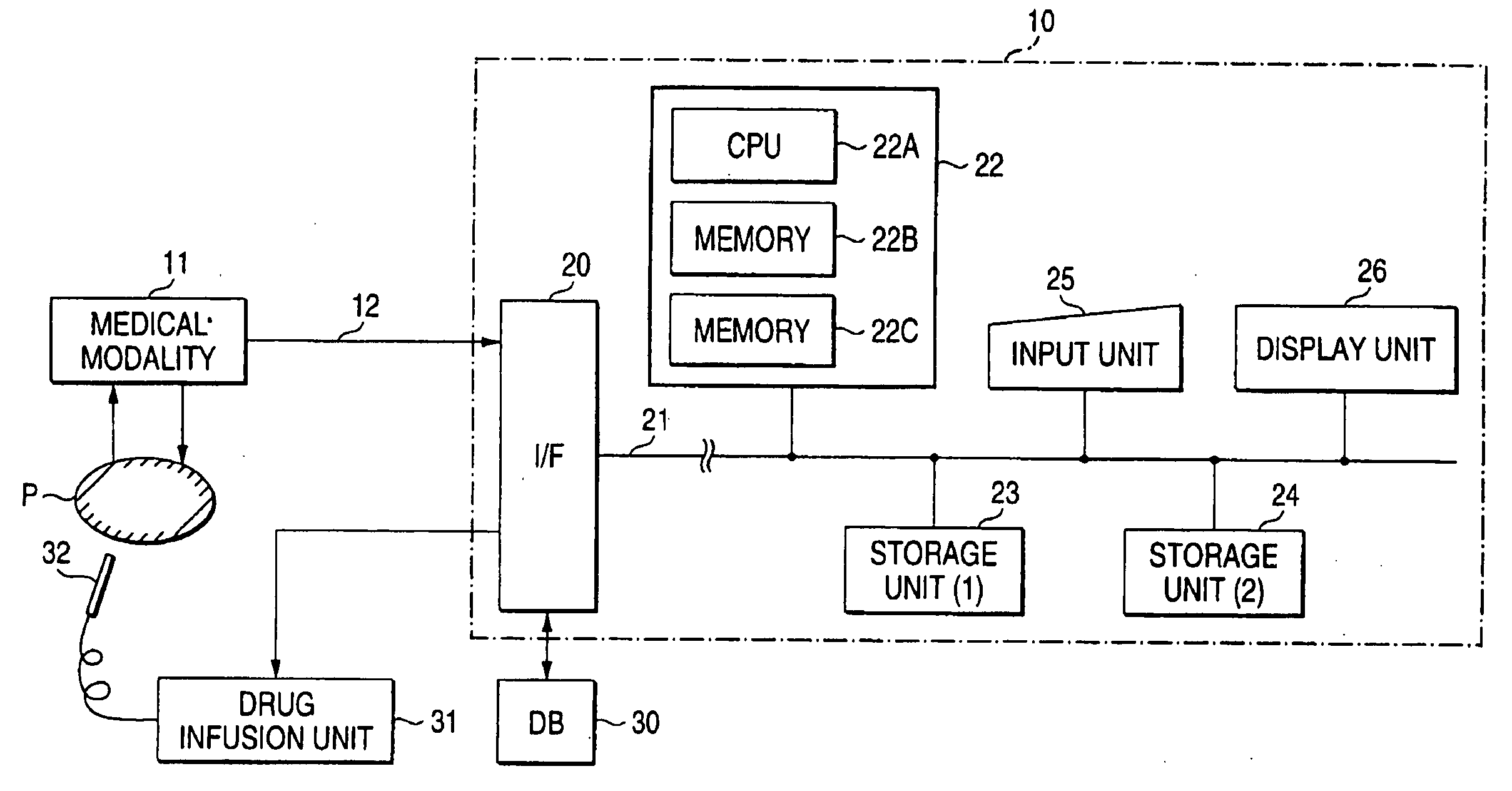
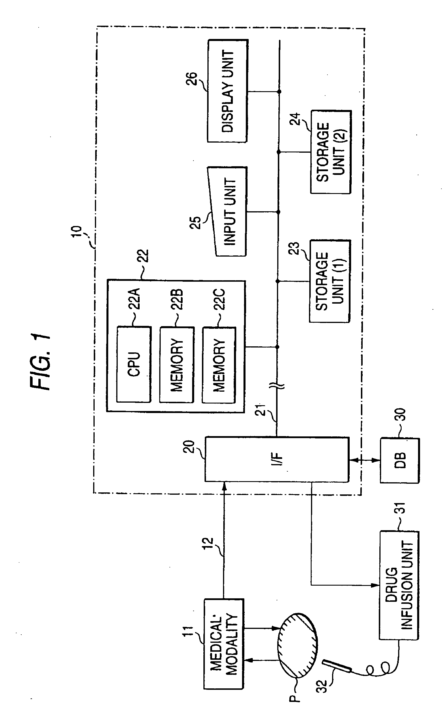
The blood-flow analysis apparatus acquires information on blood-flow dynamics from image data collected by a dynamic study method with medical modality such as a magnetic resonance imaging scanner or an X-ray CT scanner and displays it. Accordingly, the blood-flow analysis apparatus is preferably in an environment where such image data can be acquired and may be integrated with or separated from medical modality. With a separate structure, collected image data is sent from medical modality to a blood-flow analysis apparatus via a recording medium or a communication unit.

FIG. 1 shows the general outline of the blood-flow analysis apparatus according to the embodiment. The blood-flow analysis apparatus 10 receives image data of a sample P collected by a medical modality, which is imaged by a dynamic study method, via a communication unit 12 (or a recor...


PUM


Abstract

There is provided a blood-flow analysis apparatus for analyzing the time intensity curve for each pixel or region of interest of time-series images collected by photographing a desired region of a sample over time with a medical modality by applying a tracer to the blood of the sample. The analysis apparatus includes a calculation unit for calculating parameters indicative of blood-flow dynamics peculiar to the measured tissue of the sample as ratio to or difference from parameters at a desired reference region on the basis of only the time intensity curve of the measured tissue, and a visual-information presentation unit for visually presenting the calculations by the calculation unit.

Description

BACKGROUND OF THE INVENTION 1. Field of the Invention The present invention relates to an apparatus and a method for analyzing the blood-flow dynamics of a sample from image data of the sample obtained with medical diagnostic imaging apparatus such as a magnetic resonance imaging (MRI) scanner, an X-ray CT scanner, a single photon emission CT (SPECT) scanner, a positron emission CT (PET) scanner and, more particularly, it relates to an apparatus and a method for measuring blood-flow dynamics easily, quickly, and accurately using time-series continuous image data collected by applying a labeled substance which is called a tracer to the blood flow in the sample. 2. Description of the Related Art In general, in dynamic study with an X-ray CT scanner or a dynamic susceptibility contrast MRI (DSC-MRI) with a magnetic resonance imaging scanner, as described in “●stergaard L, Sorensen A G, Kwong K K, Weisskoff R M, Gyldensted C, Rosen B R; High Resolution Measurement of Cerebral Blood ...

Claims


Application Information

Patent Timeline
Patent Type & Authority Applications(United States)
IPC IPC(8): G01R33/28A61B5/00A61B5/026A61B5/055A61B6/00A61B6/03G01R33/54
CPCA61B5/0263A61B5/0275A61B6/507A61B6/504A61B6/481
Inventor KIMURA, TOKUNORI
Owner TOSHIBA MEDICAL SYST CORP
Why Eureka
Try Eureka