Threaded center line cage with funnel shaped profile

a funnel-shaped profile and threaded cage technology, applied in the field of center line threaded cages, can solve the problems of compressed vertebrae or other damage, and achieve the effects of preventing the pivoting of vertebrae, reducing volume and weight, and minimizing the surgical alteration of vertebral bones

Inactive Publication Date: 2005-03-24
JACKSON
View PDF10 Cites 62 Cited by
  • Summary
  • Abstract
  • Description
  • Claims
  • Application Information

AI Technical Summary

Benefits of technology

[0011] Therefore, the objects of the present invention include: providing an improved arrangement for placing an implant including interbody spacer structure between an adjacent pair of vertebrae to maintain a desired spacing therebetween; providing such an interbody spacer structure formed by a single, center line mounted spacer member, that is, positioned in substantial alignment with a medial plane of the body through the spine, and an end cap member connected to and cooperating with the spacer member; providing such a centerline spacer structure in which the spacer member has substantially cylindrical surfaces and is threaded for threading into a bore formed into and between mutually facing surfaces of an adjacent pair of vertebrae; providing such an arrangement in which crests of the spacer threads are substantially equal in radius along the axial length of the spacer while roots of the threads diminish in radius from near an anterior end to near an axial midpoint to provide greater support against subsidence on the anterior side of the spacer to help support adjacent vertebrae in a desired angular or lordotic relationship; providing such a structure in which the radius of the root of the threads diminishes at a constant rate from near an anterior end toward the posterior end until near the axial midline after which the radius of the thread root becomes generally constant to provide a substantially funnel shaped profile or funnel shape to the interior body or shape of the spacer formed by the thread root; providing such a structure in which the spacer member includes cylindrically concave lateral or side surfaces that join the upper and lower abutment surfaces on opposite lateral sides of the spacer member; providing such an arrangement wherein the shape and design of the interbody spacer member provides strength while reducing volume and weight; providing such a structure in which the spacer member can be either solid or partly hollow and which is provided with openings in structurally appropriate places in order to allow packing with bone chips or other bone fusion promoting materials; providing such a structure having a

Problems solved by technology

The vertebrae may also become c

Method used


Image

  • Threaded center line cage with funnel shaped profile
  • Threaded center line cage with funnel shaped profile
  • Threaded center line cage with funnel shaped profile

Examples


Embodiment Construction

[0031] As required, detailed embodiments of the present invention are disclosed herein; however, it is to be understood that the disclosed embodiments are merely exemplary of the invention, which may be embodied in various forms. Therefore, specific structural and functional details disclosed herein are not to be interpreted as limiting, but merely as a basis for the claims and as a representative basis for teaching one skilled in the art to variously employ the present invention in virtually any appropriately detailed structure.

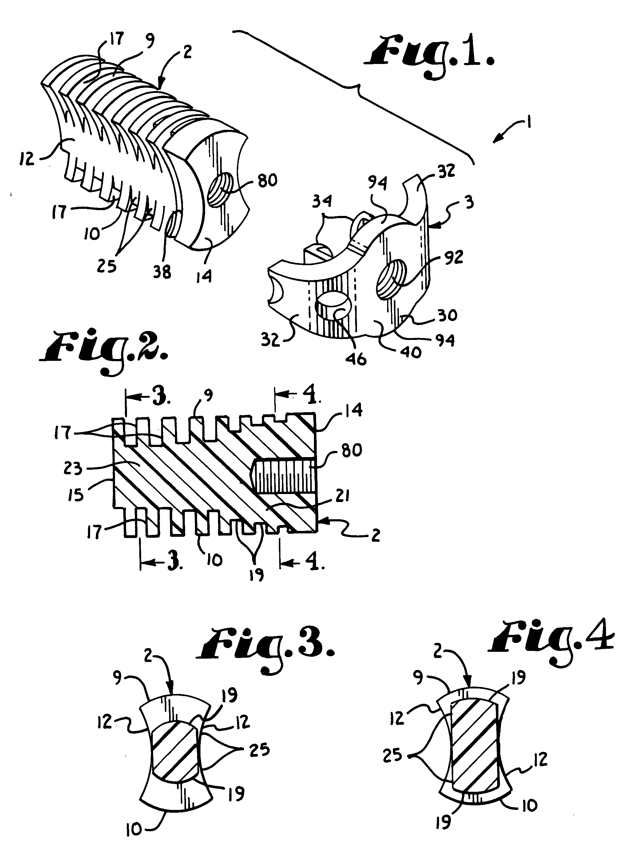
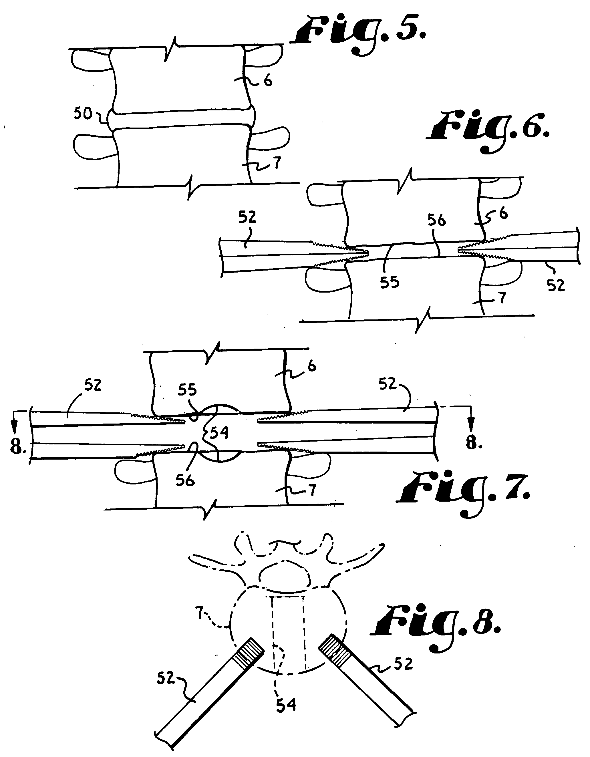
[0032] Referring to the drawings in more detail, the reference numeral 1 generally designates a threaded center line cage structure or assembly which embodies the present invention. The assembly 1 generally includes an interbody spacer member 2 and an end cap member 3 that is operably secured to the spacer member 2. The spacer member 2 and end cap 3 cooperate to maintain a beneficial spacing and mutual orientation between a pair of adjacent vertebrae 6 and ...


PUM

PropertyMeasurementUnit
Shapeaaaaaaaaaa
Radiusaaaaaaaaaa

Abstract

A threaded center line cage assembly includes a cylindrical intervertebral spacer member to which is attached a winged end cap. The spacer member is implanted along a center line or median plane between a pair of adjacent vertebrae to engage inner regions of mutually facing surfaces of the vertebrae. The end cap engages edge regions of the vertebrae to provide lateral support thereto, in cooperation with the spacer member. The spacer member is provided with threads having roots which vary in a conically diminishing manner in a posterior direction and then become constant to form an effectively funnel shaped profile to the thread roots. The funnel shaped profile of the roots tends to promote a desired lordosis between the adjacent vertebrae.

Description

BACKGROUND OF THE INVENTION [0001] The present application is directed to a center line threaded cage with a winged end cap for implantation between a pair of adjacent vertebrae in order to provide spacing, orientation, and support to the vertebrae and to promote fusion between the vertebrae. [0002] In the human spine, the pad or disc between vertebrae is sometimes damaged or deteriorates due to age, disease, injury, or congenital defect. The vertebrae may also become compressed or otherwise damaged. Because of this, surgery is often utilized to place spacers or interbody devices between the vertebrae which provide proper spacing of the vertebrae and which also promote fusion between the vertebrae. When a device of this type is utilized for purposes of promoting fusion, it is often referred to as a fusion cage or an intervertebral fusion device. When utilized to promote fusion, the interbody devices often are windowed and packed with bone fusion material to promote growth of the bon...

Claims


Application Information

Patent Timeline
IPC IPC(8): A61F2/00A61F2/02A61F2/28A61F2/30A61F2/44A61F2/46
CPCA61F2/28A61F2310/00131A61F2/30942A61F2/30965A61F2/446A61F2/4611A61F2002/30062A61F2002/305A61F2002/30576A61F2002/30604A61F2002/30774A61F2002/30858A61F2002/30863A61F2002/4619A61F2002/4627A61F2002/4629A61F2210/0004A61F2220/0025A61F2310/00017A61F2310/00023A61F2/30744
Inventor JACKSON, ROGER P.
Owner JACKSON
Why Eureka
Try Eureka