Intravascular stent having high fatigue performance

a stent and high fatigue performance technology, applied in the field of expandable endoprosthesis devices, can solve the problems of fatigue failure and particularly acute fatigue failure, and achieve the effects of maintaining compliance, facilitating longitudinal flexibility in the stent structure, and minimizing the alteration of the natural physiology

Active Publication Date: 2019-10-17
ABBOTT CARDIOVASCULAR
View PDF2 Cites 0 Cited by
  • Summary
  • Abstract
  • Description
  • Claims
  • Application Information

AI Technical Summary

Benefits of technology

[0019]The number and location of the links interconnecting adjacent cylindrical rings can be varied in order to develop the desired longitudinal flexibility in the stent structure both in the unexpanded as well as the expanded condition. These properties are important to minimize alteration of the natural physiology of the body lumen into which the stent is implanted and to maintain the compliance of the body lumen which is internally supported by the stent. Generally, the greater the longitudinal flexibility of the stent, the easier and the more safely it can be delivered to the implantation site.
[0020]In one embodiment, the Y-shaped members are formed by the link attaching to a curved portion of a valley, which then resembles the Y-shaped member. In this embodiment, there is a gradual radius on each side of the link where it connects to the curved portion of the Y-shaped member. More specifically, a smooth and gradual transition radius extends from each side of the link to the curved portion of the Y-shaped member, the radius being in the range from 0.017 to 0.022 inch (0.44 to 0.55 mm). One preferred radius is 0.019 inch (0.50 mm). These gradual and smooth transition radii provide a more ridged and stiffer scaffold area resulting in improved link structural fatigue performance.
[0021]In another embodiment, the Y-shaped members are formed by the links attaching to a curved portion of a valley, which then resembles the Y-shaped member. In this embodiment, the curved portion of the valley has a width that is less than the width of the curved portion of the peaks forming the U-shaped members. In one embodiment, the width of the curved portion of the valley of the Y-shaped member is in the range from 0.0073 to 0.0066 inch (0.185 to 0.168 mm). In one preferred embodiment, the width of the curved portion of the valley of the Y-shaped member is 0.0068 inch (0.173 mm). This Y-shaped member provides a reduced width which will experience less stress during fatigue loading, and hence result in improved Y-shaped member structural fatigue performance.
[0022]In another embodiment, the Y-shaped members are formed by the links attaching to a curved portion of a valley, which then resembles the Y-shaped member. In this embodiment, relief dimples are formed in the curved portion of the valley where the link attaches to the curved portion. Link fatigue factures can occur at the end of a straight strut segment near the link and valley junction where the material is highly stressed during fatigue loading and fatigue strength is lower due to the axially oriented material being weaker. The purpose of introducing relief dimples on the curved portion of the valley is to shift the location of this highly stressed area more into the curved portion of the valley where the circumferentially oriented material is stronger and can withstand more stress, thereby improving structural fatigue performance.

Problems solved by technology

Along with crimping and expansion forces, implanting a stent in the dynamic environment in a curved artery section causes stresses in the stent structure that can result in fatigue failure.
This fatigue failure is particularly acute in stents formed from a polymer material.

Method used


Image

  • Intravascular stent having high fatigue performance
  • Intravascular stent having high fatigue performance
  • Intravascular stent having high fatigue performance

Examples


Embodiment Construction

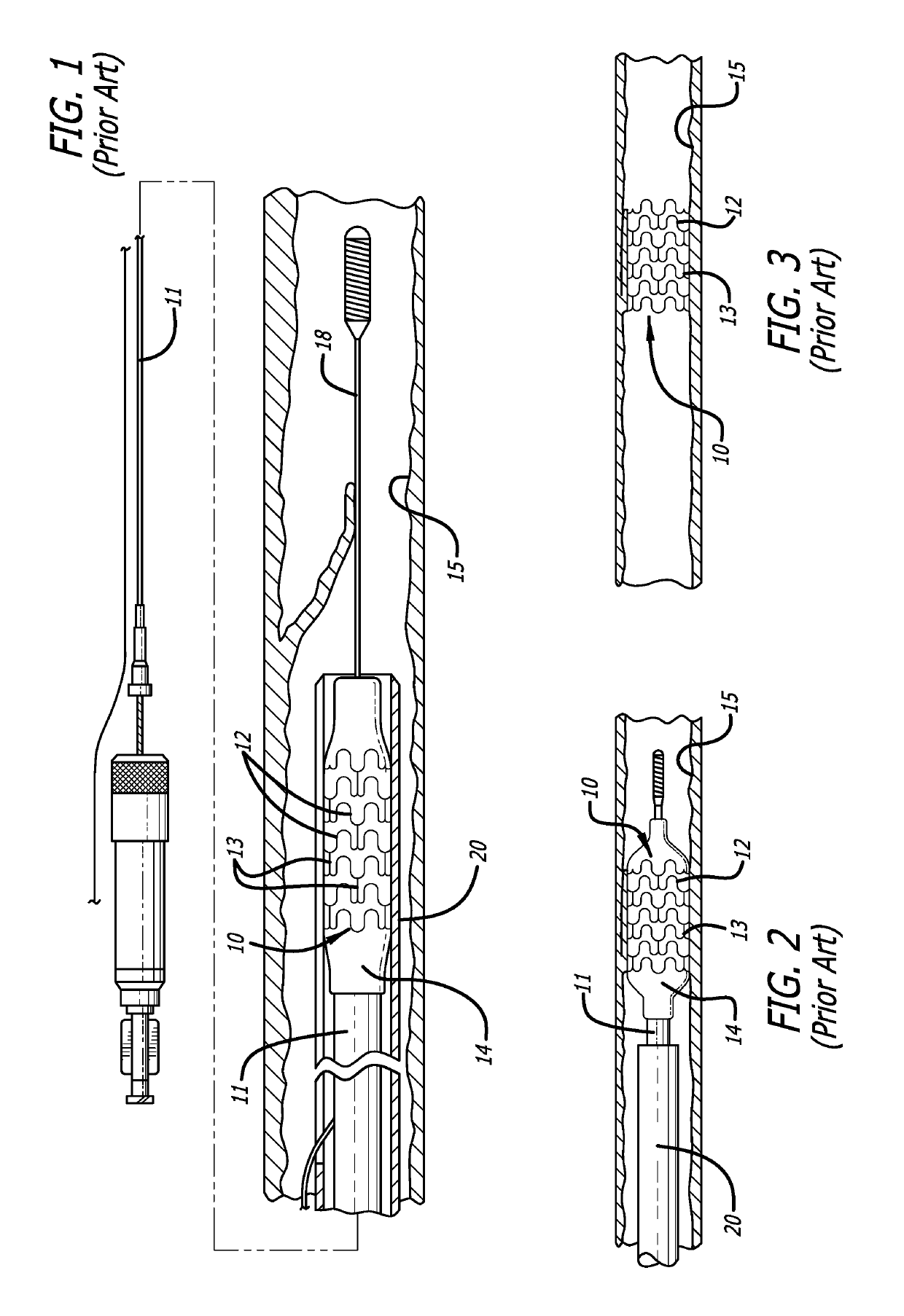
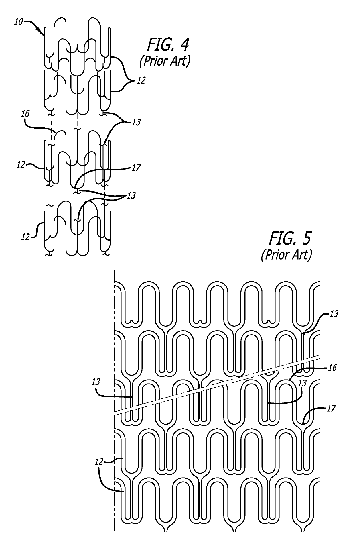
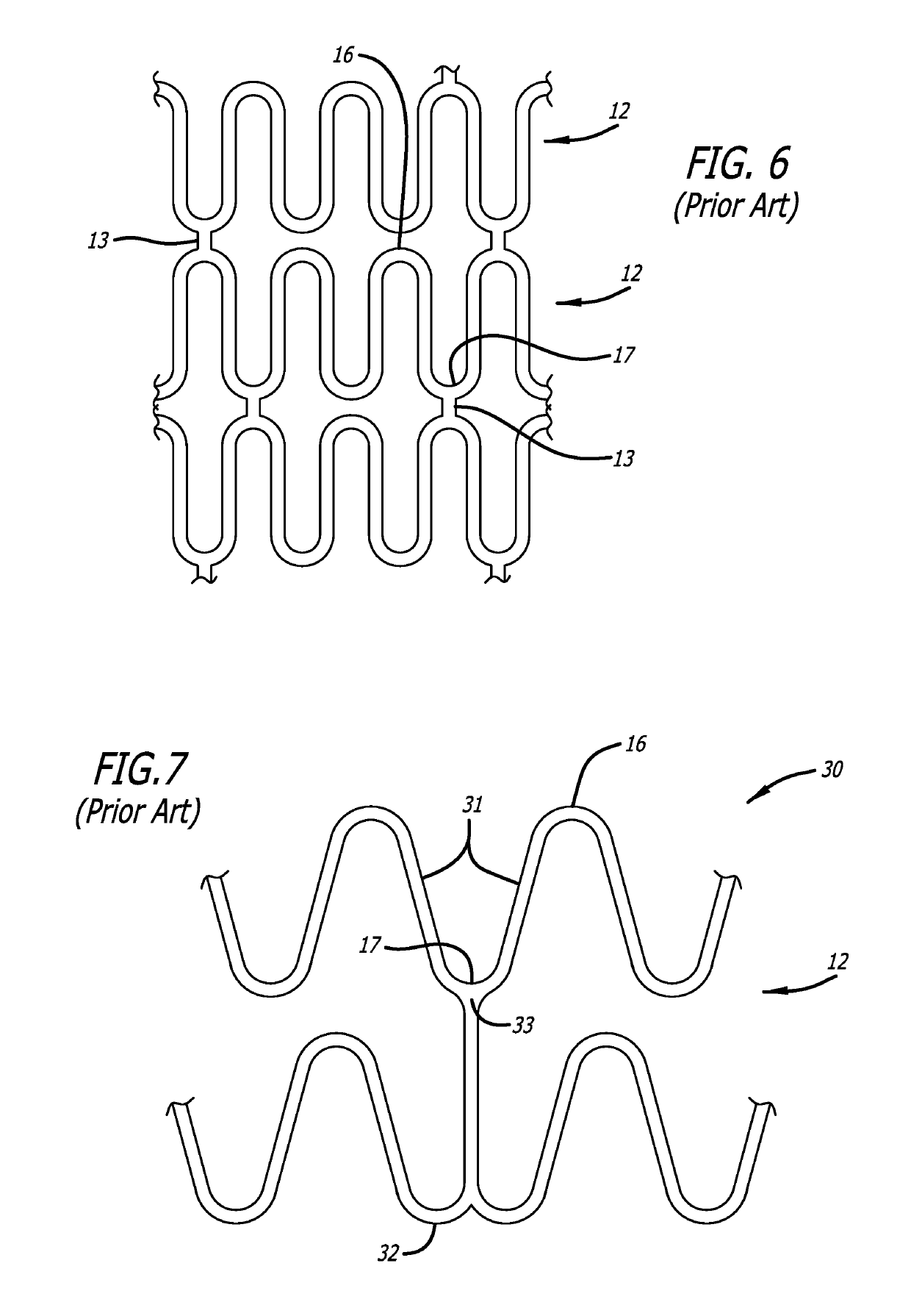
[0035]FIG. 1 illustrates a prior art stent 10 which is mounted onto a delivery catheter 11. The stent generally comprises a plurality of radially expandable cylindrical rings 12 disposed generally coaxially and interconnected by links 13 disposed between adjacent cylindrical rings. The delivery catheter 11 has an expandable portion or balloon 14 for expanding of the stent 10 within an artery 15.

[0036]The delivery catheter 11, onto which the stent 10 is mounted, is similar to a conventional balloon dilatation catheter used for angioplasty procedures.

[0037]Each radially expandable cylindrical ring 12 of the stent 10 may be independently expanded. Therefore, the balloon 14 may be provided with an inflated shape other than cylindrical, e.g. tapered, to facilitate implantation of the stent 10 in a variety of body lumen shapes.

[0038]The delivery of the stent 10 is accomplished in the following manner. The stent 10 is first mounted onto the inflatable balloon 14 on the distal extremity of ...


PUM

PropertyMeasurementUnit
radius R3aaaaaaaaaa
radius R3aaaaaaaaaa
reversed radius R4aaaaaaaaaa

Abstract

The invention is directed to an expandable stent for implantation in a body lumen, such as an artery, and a method for making it from a single length of tubing. The stent consists of a plurality of radially expandable cylindrical elements generally aligned on a common axis and interconnected by one or more links. A Y-shaped member comprised of a link and a U-shaped member has relief dimples formed in the curved portion of a valley to reduce localized stress and thereby reduce fatigue failure that can lead to link structure failure.

Description

BACKGROUND[0001]This invention relates to expandable endoprosthesis devices, generally called stents, which are adapted to be implanted into a patient's body lumen, such as blood vessel, to maintain the patency thereof. These devices are very useful in the treatment of atherosclerotic stenosis in blood vessels.[0002]Various means have been described to deliver and implant stents. One method frequently described for delivering a stent to a desired intraluminal location includes mounting the expandable stent on an expandable member, such as a balloon, provided on the distal end of an intravascular catheter, advancing the catheter to the desired location within the patient's body lumen, inflating the balloon on the catheter to expand the stent into a permanent expanded condition and then deflating the balloon and removing the catheter.[0003]The stent must be able to satisfy a number of mechanical requirements. First, the stent must be capable of withstanding the structural loads, namel...

Claims


Application Information

Patent Timeline
Patent Type & Authority Applications(United States)
IPC IPC(8): A61F2/89
CPCA61F2210/0004A61F2230/006A61F2/89A61F2230/0069A61F2/958A61F2230/0013A61F2230/0056A61F2/915A61F2002/91575A61F2002/828
Inventor TA, DIEM UYENESWARAN, SENTHIL KUMAR
Owner ABBOTT CARDIOVASCULAR
Why Eureka
Try Eureka