High strength member for intracorporeal use

a high-strength, intracorporeal technology, applied in the field of intravascular members, can solve problems such as specimens, achieve the effects of maintaining compliance, facilitating insertion, and minimizing the alteration of natural physiology

Inactive Publication Date: 2010-06-10
ABBOTT CARDIOVASCULAR
View PDF49 Cites 0 Cited by
  • Summary
  • Abstract
  • Description
  • Claims
  • Application Information

AI Technical Summary

Benefits of technology

[0024]The number and location of elements interconnecting adjacent cylindrical elements can be varied in order to develop the desired longitudinal flexibility in the stent structure both in the unexpanded as well as the expanded condition. These properties are important to minimize alteration of the natural physiology of the body lumen into which the stent is implanted and to maintain the compliance of the body lumen which is internally supported by the stent. Generally, the greater the longitudinal flexibility of the stent, the easier and the more safely it can be delivered to the implantation site.
[0025]In a presently preferred embodiment of the invention the stent is conveniently and easily formed by coating stainless steel hypotubing with a material resistant to chemical etching, and then removing portions of the coating to expose portions of underlying tubing which are to be removed to develop the desired stent structure. The exposed portions of the tubing are removed by chemically etching from the tubing exterior leaving the coated portion of the tubing material in the desired pattern of the stent structure. The etching process develops smooth openings in the tubing wall without burrs or other artifacts which are characteristic of mechanical or laser machining processes in the small sized products contemplated. Moreover, a computer controlled laser patterning process to remove the chemical resistive coating makes photolithography technology adaptable to the manufacture of these small products. The forming of a mask in the extremely small sizes needed to make the small stents of the invention would be a most difficult task. A plurality of stents can be formed from one length of hypotubing by repeating the stent pattern and providing small webs or tabs to interconnect the stents. After the etching process, the stents can be separated by severing the small webs or tabs which connect them. The stents may further be electrochemically polished in an aqueous solution and treated, if desired by applying a biocompatible coating.

Problems solved by technology

Other methods for determining the stress-strain relationship, e.g., applying a bending moment to a cantilevered specimen, provide a different relationship from the relationship determined by tensile testing, because the stresses which occur in the specimen during bending are not as uniform as they are in tensile testing.

Method used


Image

  • High strength member for intracorporeal use
  • High strength member for intracorporeal use
  • High strength member for intracorporeal use

Examples


Embodiment Construction

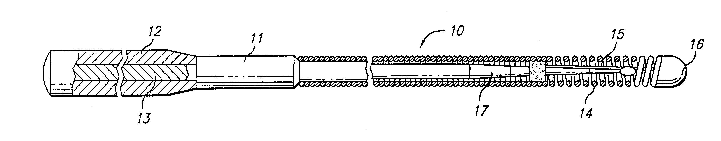
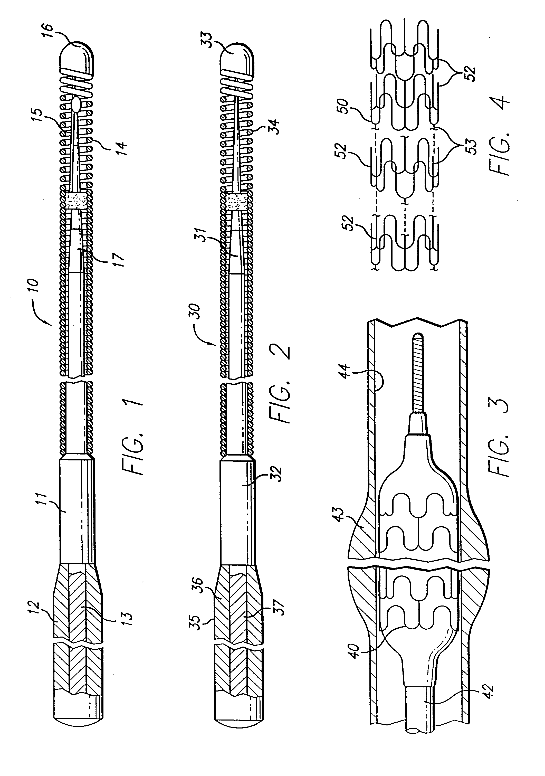
[0038]FIG. 1 illustrates a guidewire 10 which includes a core member 11 having an outer sheath 12 formed of a Co—Ni—Cr alloy and an inner member 13 formed of Ni—Ti, a helical coil 14 on the distal end of the core member with a shaping ribbon 15 extending between the distal end of the core member and a rounded plug 16 which connects the distal end of the shaping ribbon with the distal end of the helical coil. The distal section 17 of the core member 11, which is disposed primarily within the coil 14, is tapered to sequentially smaller diameters to provide gradually increasing flexibility along the length of the distal portion of the guidewire 10. The taper is formed by removing the sheath 12 formed of high strength Co—Ni—Cr alloy which exposes the inner NiTi alloy member 13 having moderate strength and substantial flexibility which may then be ground in a conventional manner to one or more smaller diameter sections.

[0039]FIG. 2 depicts a guidewire 30 with a construction wherein the t...


PUM

PropertyMeasurementUnit
weight percentaaaaaaaaaa
height-to-width aspect ratioaaaaaaaaaa

Abstract

This invention is directed to an intracorporeal device formed of a high strength Co—Ni—Cr alloy and is particularly suitable for forming a composite product with a pseudoelastic member formed of NiTi alloy. Suitable intracorporeal products include guidewires and stents. The high strength alloy consists essentially of about 28 to about 65% cobalt, about 2 to about 40% nickel, about 5 to about 35% chromium, up to about 12% molybdenum, up to about 20% tungsten, up to about 20% iron and the balance inconsequential amounts of impurities and other alloying constituents, with a preferred alloy composition including about 30 to about 45% cobalt, about 25 to about 37% nickel, about 15 to about 25% chromium and about 5 to about 15% molybdenum. Intravascular devices such as guidewires, stents and the like can be formed of this high strength Co—Ni—Cr alloy.

Description

RELATED APPLICATIONS[0001]This is a continuation application of co-pending application having U.S. Ser. No. 10 / 154,474, filed May 23, 2002; which is a continuation of U.S. Ser. No. 09 / 071,680, filed May 1, 1998; which is divisional of U.S. Ser. No. 08 / 829,465, filed Mar. 28, 1997; which is a continuation of U.S. Ser. No. 08 / 280,209, filed on Jun. 25, 1994; all of whose contents are hereby incorporated by reference.BACKGROUND OF THE INVENTION[0002]This invention relates to the field of intracorporeal medical devices, and more particularly to elongated intravascular members such as guidewires for percutaneous transluminal coronary angioplasty (PTCA) and stents for maintaining body lumen patency after the body lumen has been dilated with a balloon.[0003]In PTCA procedures a guiding catheter is percutaneously introduced into the cardiovascular system of a patient in a conventional Seldiger technique and advanced therein until the distal tip of the guiding catheter is seated in the ostiu...

Claims


Application Information

Patent Timeline
Patent Type & Authority Applications(United States)
IPC IPC(8): C25F3/22B23H9/00B23H5/00A61F2/00A61F2/06A61F2/84A61M25/00A61M25/09
CPCA61F2/958A61F2210/0019A61M2025/09083A61M25/0012A61M25/09A61M25/0009
Inventor FARIABI, SEPEHR
Owner ABBOTT CARDIOVASCULAR
Why Eureka
Try Eureka