
Method of repairing spline and seal teeth of a mated component

a technology of mated components and seal teeth, which is applied in the direction of liquid fuel engines, machines/engines, manufacturing tools, etc., can solve the problems of reducing the service life of parts, splines on the shaft transmit load and experience wear, and material stock loss, so as to minimize the alteration of physical properties and reduce heat input.

Inactive Publication Date: 2009-09-22
GENERAL ELECTRIC CO
View PDF103 Cites 0 Cited by
  • Summary
  • Abstract
  • Description
  • Claims
  • Application Information

AI Technical Summary

Benefits of technology

"The present invention provides a method for repairing spline teeth of a mated component by welding a minimal amount of repair material to a surface that opposes the worn area, while providing a full metallurgical bond between the repair material and the substrate. This method allows for the repair of a component without altering its physical properties adjacent to the weld repair area. The invention also provides a method for repairing a gas turbine engine component by welding a repair material to a non-contact surface portion and machining the contact surface portion to a desired contour, thereby removing at least a portion of the contact surface portion. The technical effects of the invention include minimizing the alteration of physical properties adjacent a weld repair area and achieving a full metallurgical bond between the repair material and the substrate."

Problems solved by technology

As the engine is operated normally, the splines on the shaft transmit loads and experience wear, generally on a single face.
This wear on the load transmitting, or pressure, face of the splines can cause loss of material stock, the creation of a stress riser on the pressure face and reduction of service life of the part, eventually necessitating an engine rebuild.
Excessive spline wear could result in failure of both the splines and the engine.
One reason for scrapping the shaft is the lack of adequate repair methods for the worn spline teeth.
Efforts to repair the worn face of shaft splines by welding a filler material to the worn face and remachine this face have resulted in a repaired shaft whose dimensions are restored, but have inadequate material properties on the pressure face of the spline.
One of these inadequate properties is an undesirable change in grain size within the heat affected zone (HAZ) of the weld area.
A larger grain size is associated with lower fatigue life and results in a material microstructure that is more susceptible to cracking and will withstand less cyclic stress.
Fatigue cracking on the pressure face of splines are a known cause of premature failure.

Method used


Image

  • Method of repairing spline and seal teeth of a mated component
  • Method of repairing spline and seal teeth of a mated component
  • Method of repairing spline and seal teeth of a mated component

Examples


Embodiment Construction

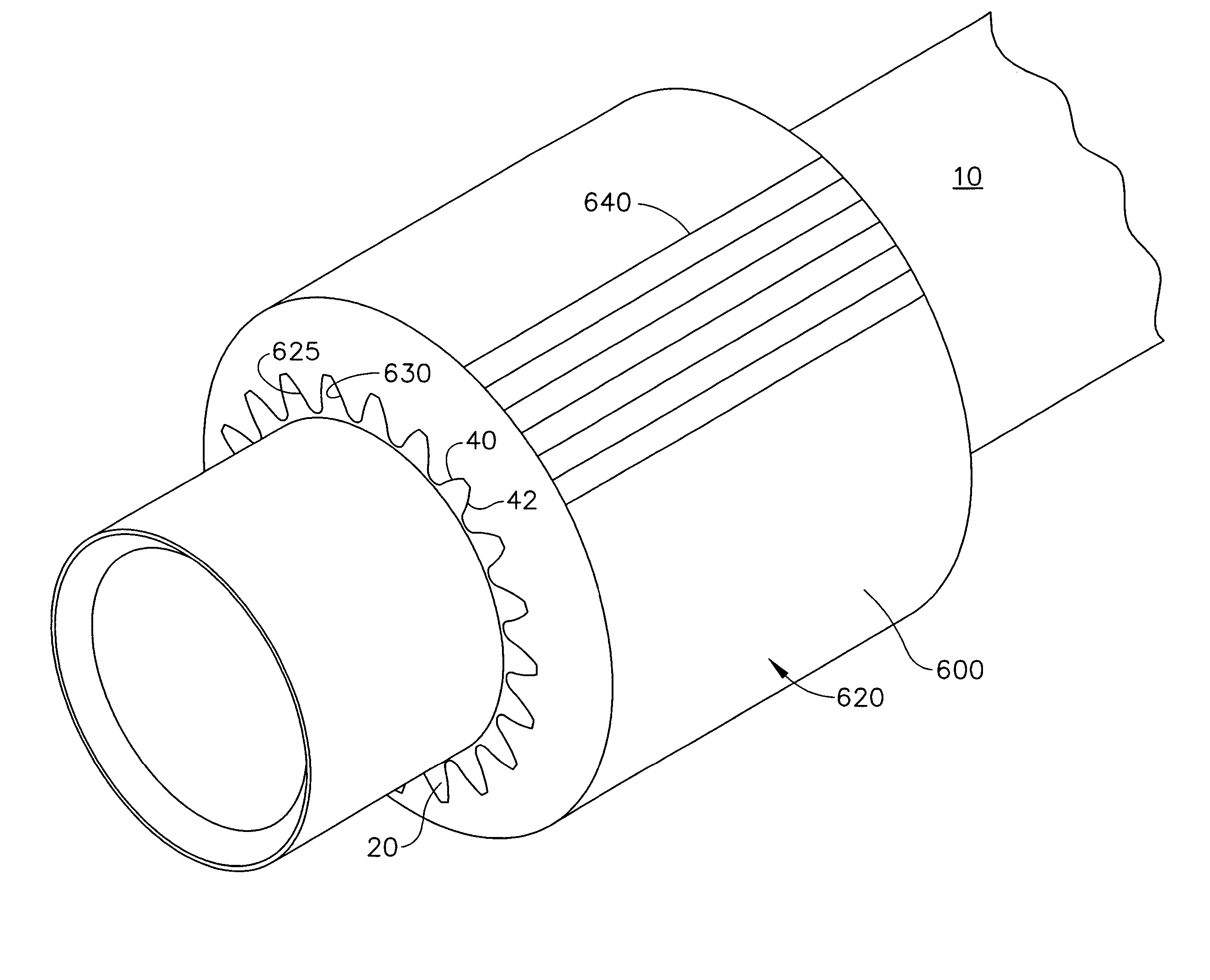
[0020]While exemplary embodiments of the invention will be discussed primarily with respect to a power turbine shaft of a gas turbine engine, it will be appreciated that the invention can be used with respect to any mated component having splines or seal teeth that matingly engage a corresponding, complementary mated component.

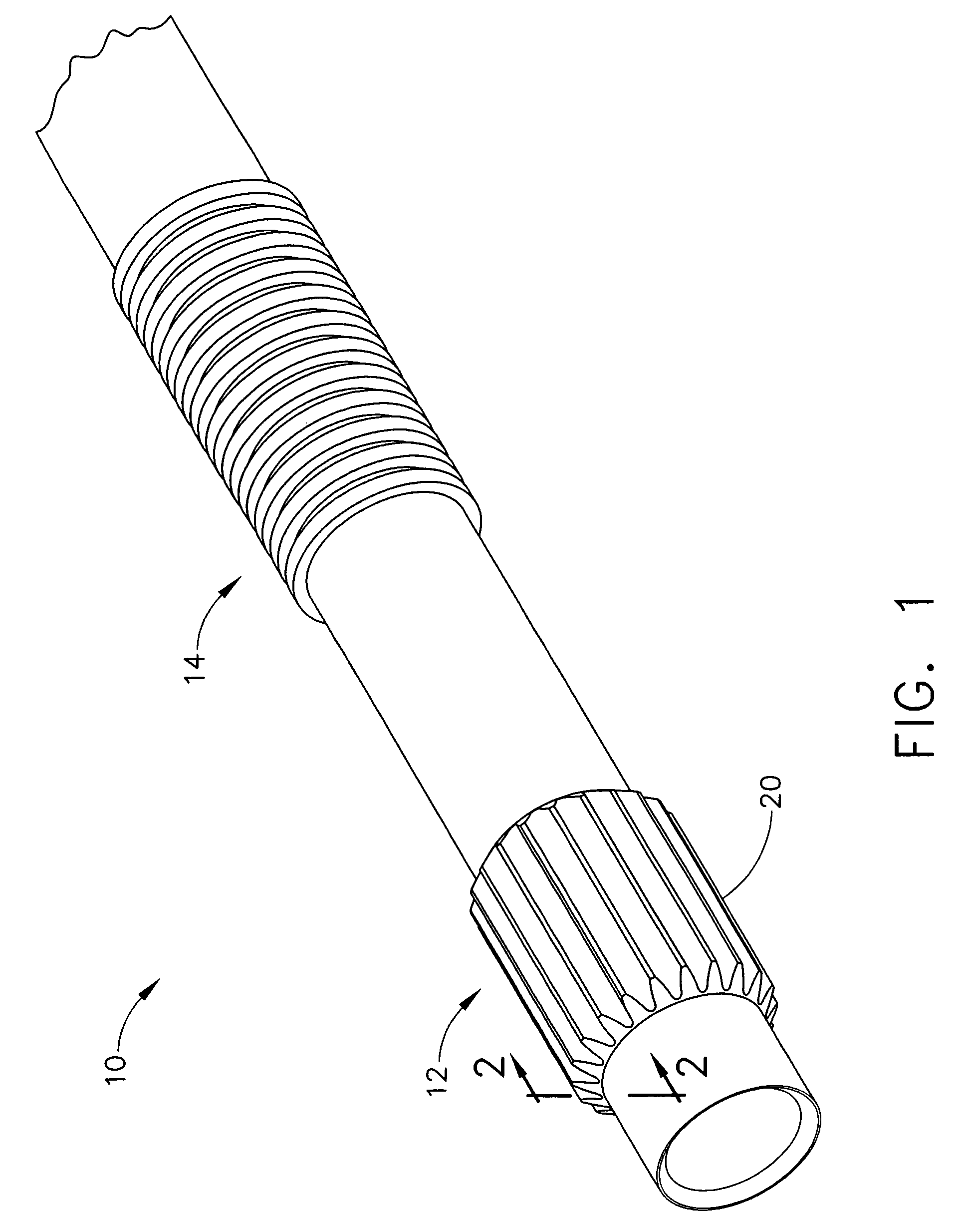
[0021]FIG. 1 illustrates a power turbine shaft 10 of an aircraft engine (not shown) to include a splined portion 12 and a seal portion 14. Splined portion 12 includes a plurality of splines 20 aligned substantially parallel to the axis of shaft 10 and radially spaced about shaft 10.

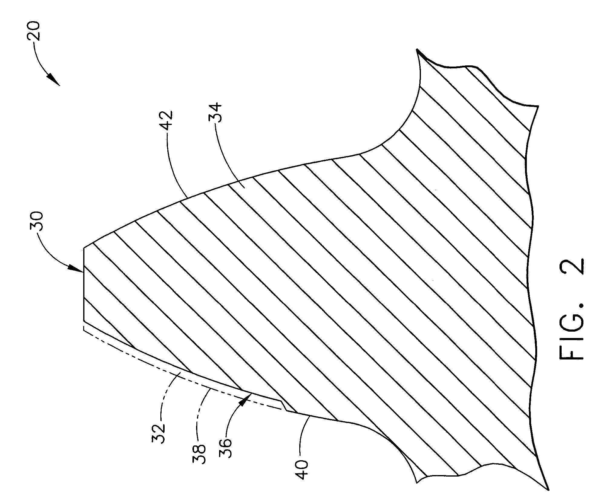
[0022]With reference to FIG. 2, a spline 20 is illustrated. Spline 20 has an exterior surface 30 that defines a typical repair area, or worn portion, 32 and a non-worn portion 34. Worn portion 32 is defined by a phantom line 38 and a worn surface 36. Before use within an aircraft engine, spline 20 was manufactured to dimensions defined by phantom line 38 and exterior surface 30. Dur...


PUM


Abstract

A method of repairing spline and seal teeth of a mated component is disclosed. The method includes a low energy input weld to deposit a repair material on the non-worn, non-pressure face of the splines while minimizing the HAZ grain size. The splined area of the component is then remachined to the original spline contour by removing original material from the worn, pressure face of the splines and excess repair material to produce a mated component with radially re-clocked splines that have original component material on the pressure face of the teeth.

Description

RELATED APPLICATIONS[0001]This Application is related to U.S. application Ser. No. 11 / 104,214 entitled “Overlay for Repairing Spline and Seal Teeth of a Mated Component” and to U.S. application Ser. No. 11 / 104,171 entitled “Repaired Spline and Seal Teeth on Mated Components” both of which are assigned to the Assignee of the present invention and which were also filed Apr. 12, 2005, the contents of which are hereby incorporated by reference in their entirety.FIELD OF THE INVENTION[0002]The present invention relates generally to repair of mated components. More particularly, this invention is directed to the repair of spline and seal teeth for an aircraft engine shaft.BACKGROUND OF THE INVENTION[0003]A gas turbine engine includes a compressor that provides pressurized air to a combustor wherein the air is mixed with fuel and burned for generating hot combustion gasses. These gasses flow downstream to one or more turbines that extract energy therefrom to power the compressor and provid...

Claims


Application Information

Patent Timeline
Patent Type & Authority Patents(United States)
IPC IPC(8): B23P6/00
CPCF01D5/005F01D5/026B23P6/00B23P6/007F16D2001/103F05D2240/60Y10T29/49318Y10T29/49734Y10T29/49728Y10T29/49746Y10T29/49732Y10T29/49737Y10T29/49742F05D2260/4031
Inventor FINTON, TROY LANCEKELLY, THOMAS JOSEPHLUTZ, KENNETH ERIC
Owner GENERAL ELECTRIC CO
Learn More