
Enterprise resource planning system with integrated vehicle diagnostic and information system

Inactive Publication Date: 2005-03-24
SNAP ON INC
View PDF12 Cites 548 Cited by
  • Summary
  • Abstract
  • Description
  • Claims
  • Application Information

AI Technical Summary

Problems solved by technology

The first of these includes very limited in-vehicle diagnostics displays (such as oil-pressure gauges and “check engine” indicators).
While these systems function well, they have operational limits that can result in extra cost and downtime for the vehicle.
For example, the in-vehicle diagnostics displays often reveal problems only after they have become serious, while there may have been early indications of a problem forming that could have been revealed by more sophisticated tools.
While these vehicle diagnostic systems provide a centrally located method for communicating with and maintaining centralized records of activities of a vehicle, some drawbacks exist.
These proprietary and non-standard customized software applications suffer from not being able to support (i) more than one type of platform, (ii) standard operating systems, (iii) widely used embedded computers, Windows portable devices, and PalmOS devices, and (iv) other standardized frameworks.
In addition to the cost of such additional applications, customers may have to pay for the incremental cost of the vehicle information system's users (typically a service station or other attendant) time for switching between applications for each of the differing vehicle controllers.
As the number of vehicle controllers and the wage of a user increases, this incremental cost may be quite substantial.
As such, legacy systems provided customized solutions for each specific software platform used on the mobile unit or central computer, which has resulted in many legacy systems being locked into a single comprehensive, non-distributed and non-scalable customized solution as the difficulty of accommodating all applications and networks is difficult.
As a result of the foregoing drawbacks, legacy vehicle diagnostic systems are not good candidates for integration into an enterprise-resource planning (ERP) system.

Method used


Image

  • Enterprise resource planning system with integrated vehicle diagnostic and information system
  • Enterprise resource planning system with integrated vehicle diagnostic and information system
  • Enterprise resource planning system with integrated vehicle diagnostic and information system

Examples


Embodiment Construction

[0065] 1 System Overview

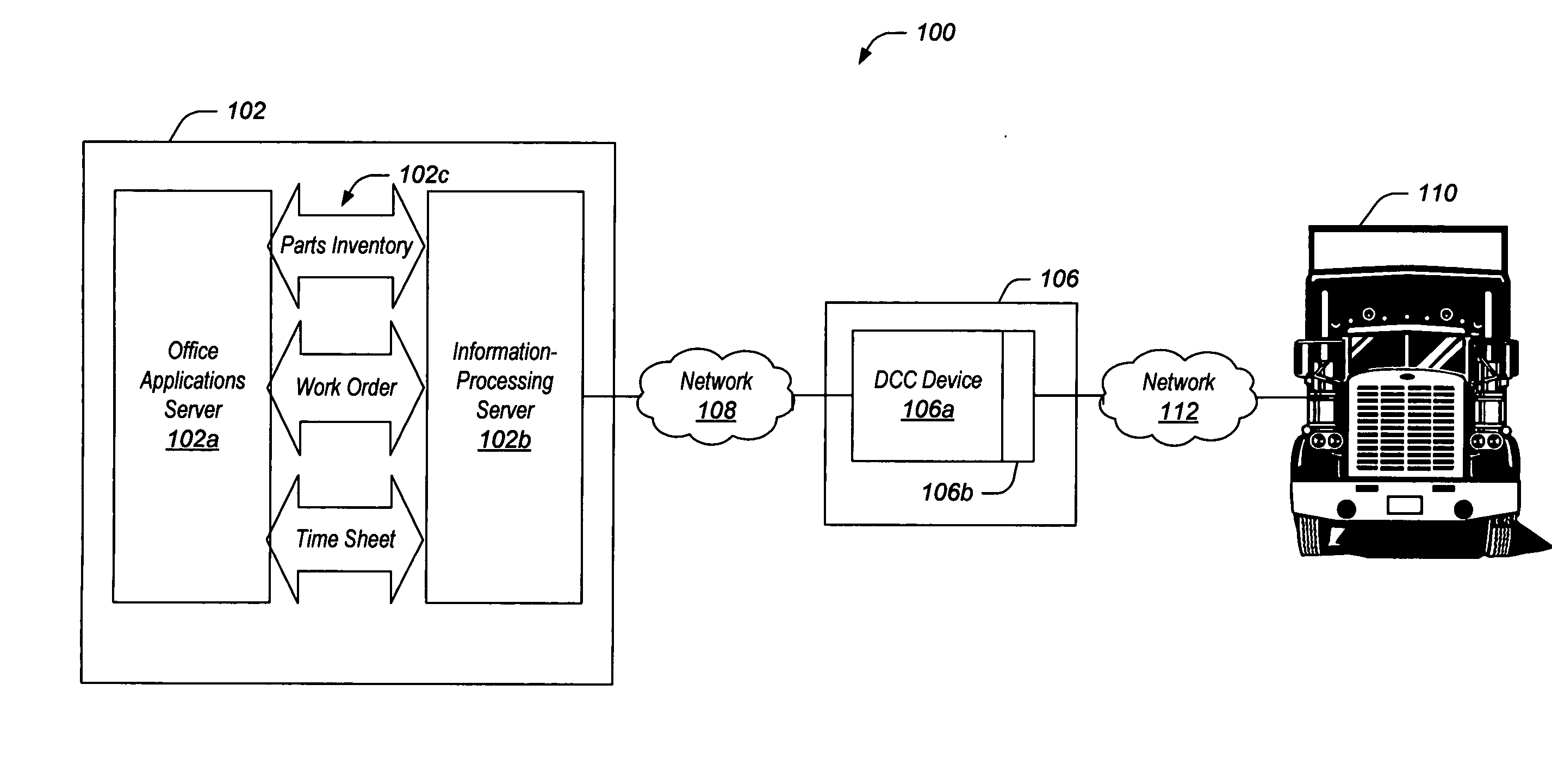
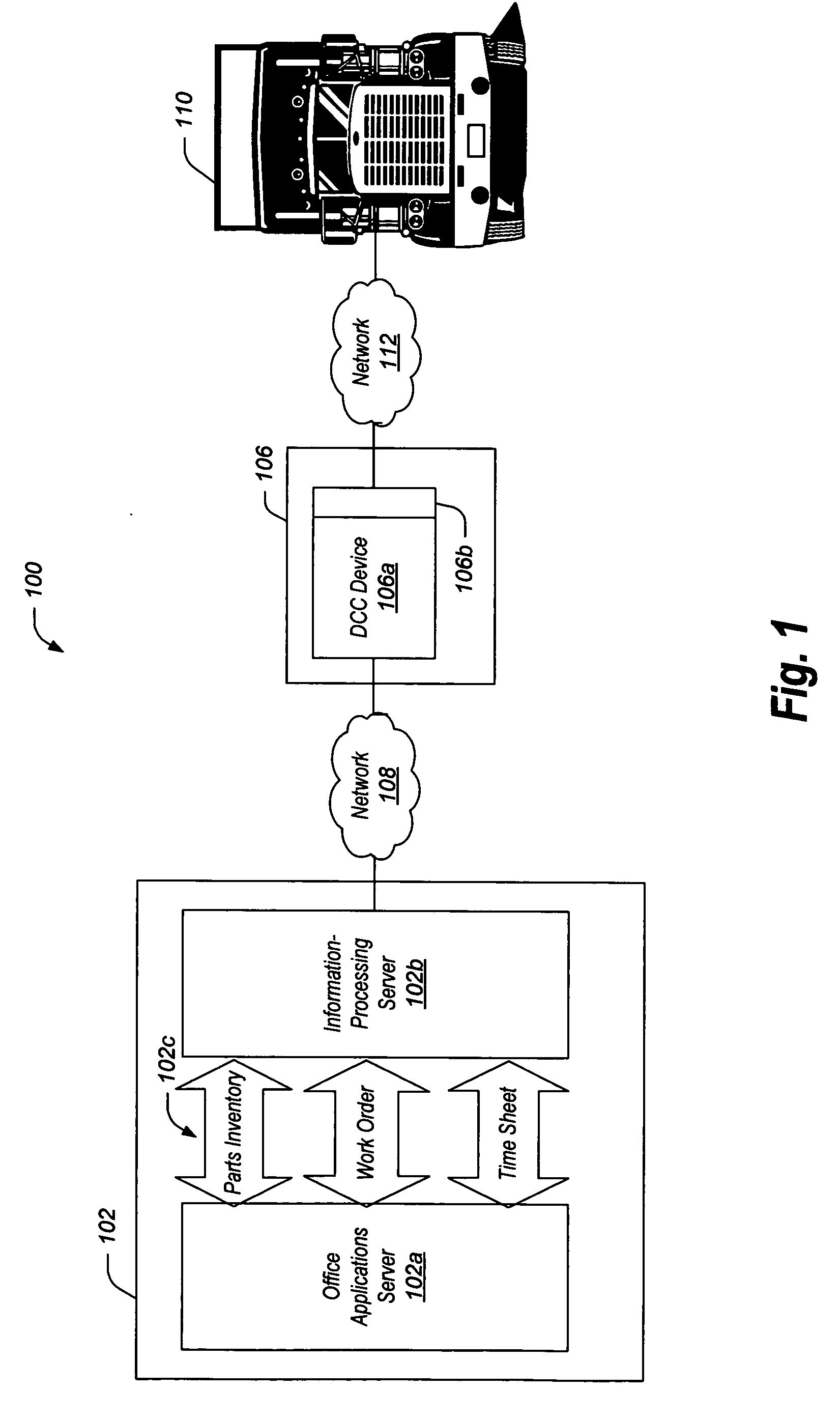
[0066]FIG. 1 is a block diagram of an enterprise-resource planning (ERP) system 100 in which information processing and data management may be integrated or otherwise combined with a vehicle diagnostic and information system, such as the vehicle diagnostic and information system (VDIS) 106. Deployment of the ERP system 100 may offer to vehicle repair facilities a substantial cost savings, improved workflow, and higher customer and employee satisfaction as compared to disparate and stand-alone silos of such legacy processes and systems. Included in the ERP system 100 is an enterprise information management system (EIMS) 102 which is communicatively coupled to the VDIS 106 via an integration communication link or network 108.

[0067] Through the deployment of the EIMS 102, the VDIS 106, and the communication network 108, the ERP system 100 may beneficially provide a highly adaptable and extensible system that not only delivers enhanced diagnostics over traditio...


PUM


Abstract

An enterprise-resource planning (ERP) system in which information processing and data management may be integrated or otherwise combined with a vehicle-diagnostic-and-information system is provided. The ERP system includes a first device for obtaining vehicle characteristic information from a vehicle, and a second device for integrating the vehicle characteristic information into an information management system. The first device is adapted to send the vehicle characteristic information over a communication link. The second device is adapted to receive from the first device over the communication link the vehicle characteristic information. When the second device integrates the vehicle diagnostic information into the information management system, the first and second devices are operable to function as the ERP system.

Description

CROSS REFERENCE TO RELATED APPLICATIONS [0001] The present application: [0002] (1) claims the benefit of U.S. Provisional App. Ser. No. 60 / 473,226, entitled “Vehicle Diagnostic, Prognostic and Telematic System”, filed May 23, 2004; [0003] (2) is a continuation-in-part, claiming the benefit of commonly assigned, co-pending U.S. patent application Ser. No. ______, filed concurrently herewith, entitled “Wireless Communication Framework” (attorney docket 03-078-A1); which is a continuation of PCT Patent App. Ser No. US04 / 11326, entitled “Wireless Communication Framework,” filed Apr. 12, 2004; which: [0004] (i) is a continuation-in-part, claiming the benefit of commonly assigned, co-pending U.S. patent application Ser. No. 10 / 091,096, filed Mar. 4, 2002, entitled “Remote Monitoring, Configuring, Programming and Diagnostic System and Method for Vehicles and Vehicle Components,” which is a continuation-in-part, claiming the benefit of commonly assigned, co-pending U.S. patent application S...

Claims


Application Information

Patent Timeline
IPC IPC(8): G01C22/00G06FG06F19/00
CPCG07C5/008G06Q10/00
Inventor SMITHNEYMEYER, NIKESSENMACHER, DENNISMEADE, TRACYLOHR, REBECCAREDDY, SUNILVENKATA, MADANAKIRK, COREY
Owner SNAP ON INC
Learn More