Solar energy collection system

Inactive Publication Date: 2005-03-31
COBERT DAVID M
View PDF12 Cites 6 Cited by
  • Summary
  • Abstract
  • Description
  • Claims
  • Application Information

AI Technical Summary

Benefits of technology

[0007] It is therefore an object of this invention to provide a simpler less complex and less expensive system for concentrating solar energy onto a solar cell to generate electrical energy;
[0008] It is a further object of this invention to provide a solar energy collection sys

Problems solved by technology

Such prior art devices generally require the tracking of the sun both in longitude and latitude on a daily and seasonal b

Method used


Image

  • Solar energy collection system
  • Solar energy collection system
  • Solar energy collection system

Examples


Example

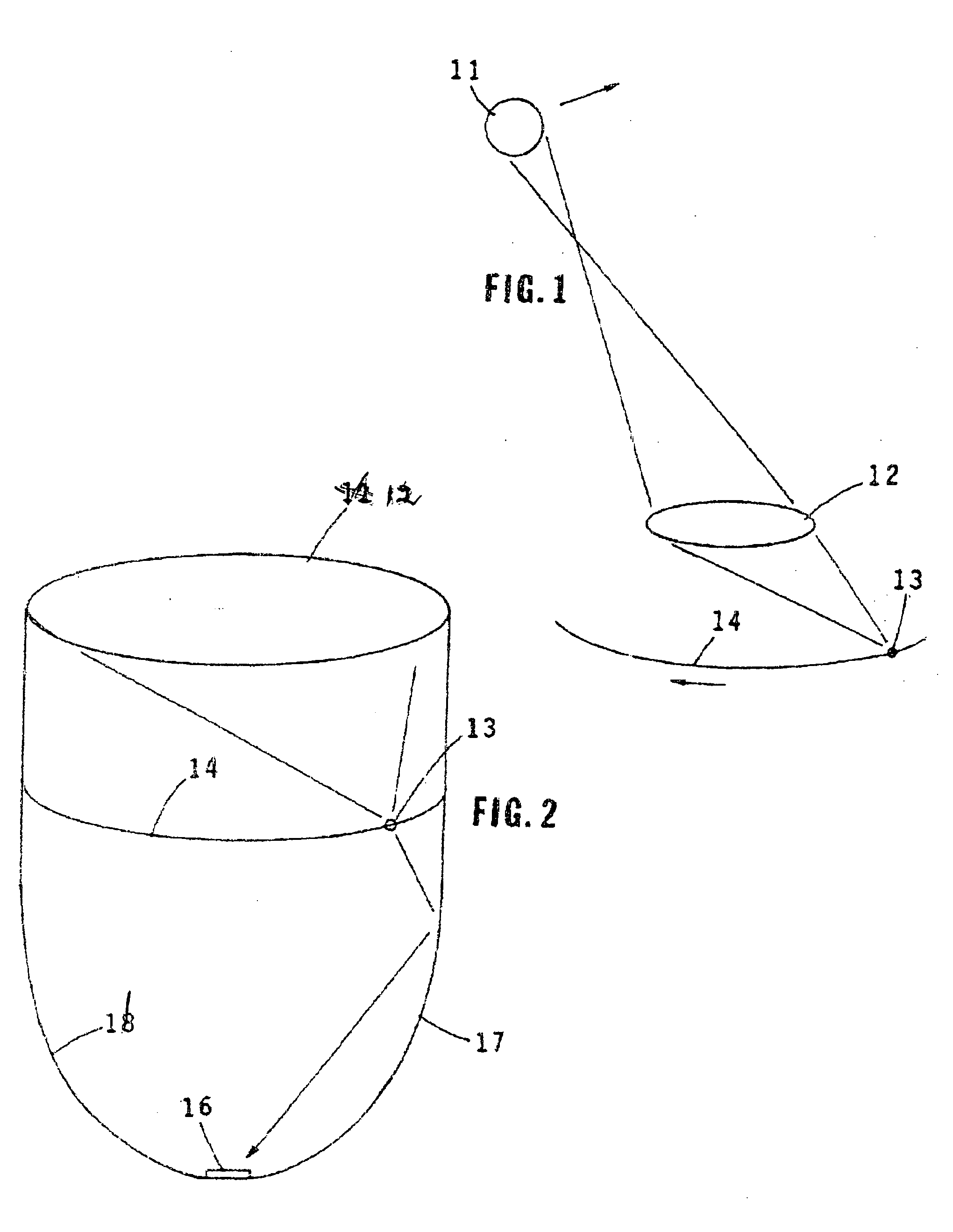
[0015] Referring to FIG. 1, a schematic drawing illustrating the operation of the system of the invention is shown. The rays of the sun strike lens 12, which is a standard magnifying lens and are focused onto a spot 13 which is within a compartment or trap. The lens is fixed at a tilt angle which is in accordance with the latitude of the site. The daily arc of the sun across the face of the lens produces a smooth arc path 14 in three dimensional space. At or near this arc path is either a secondary mirrored surface or an opening to guide the light into the solar trap.

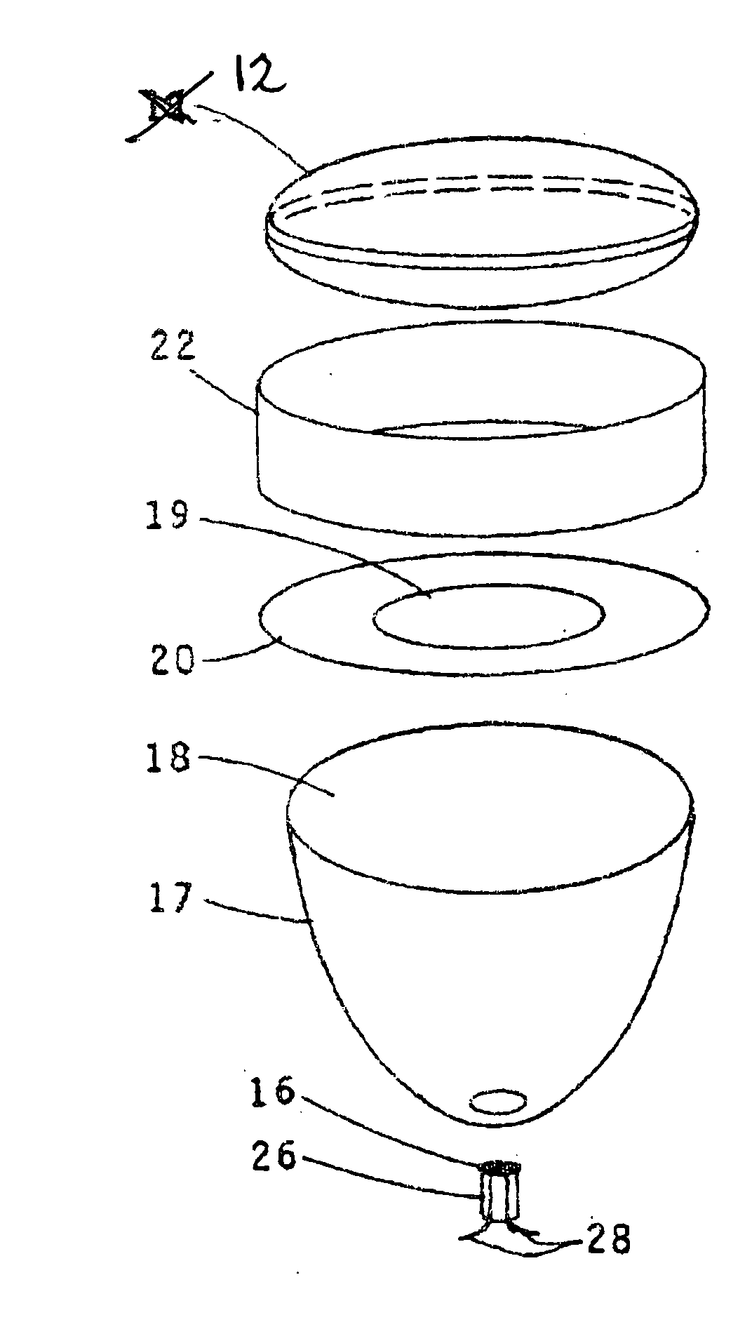
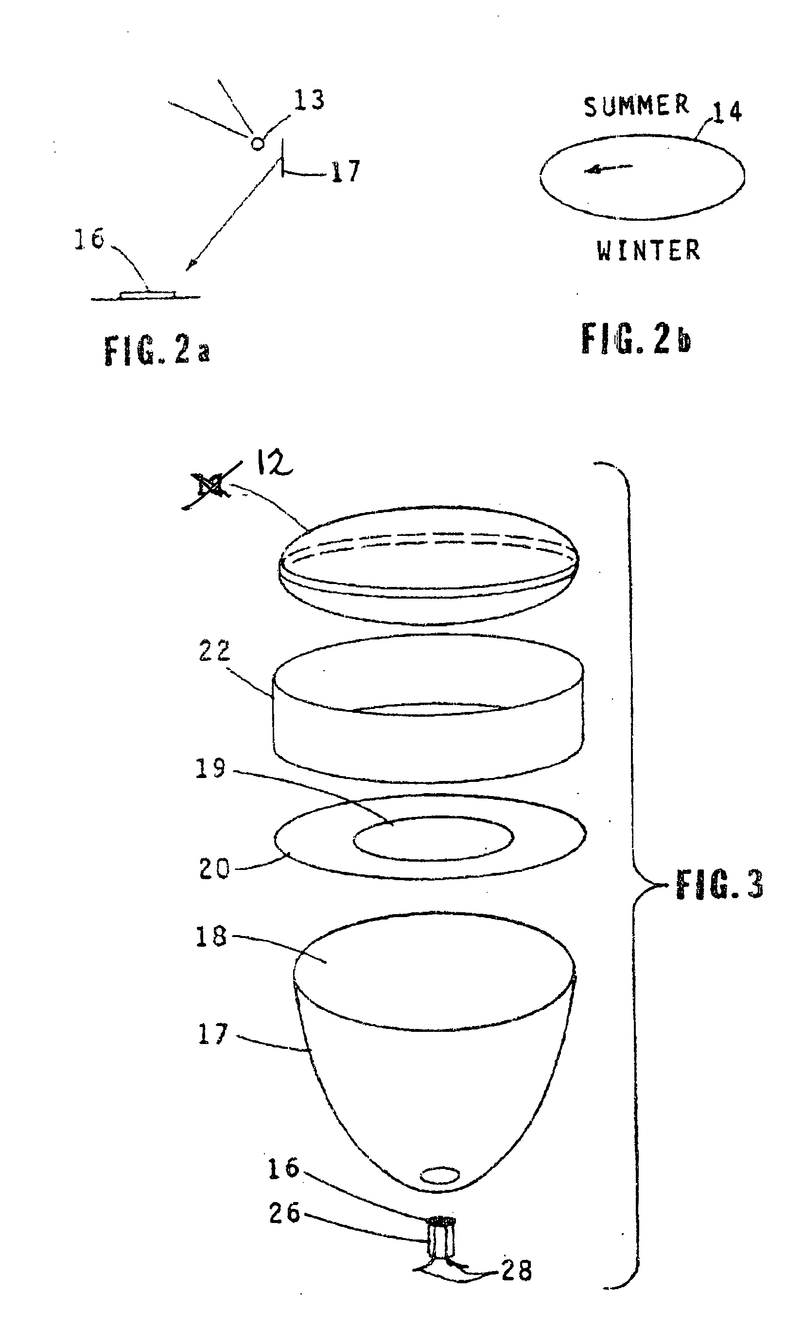
[0016] Referring now to FIGS. 2, 2A and 2B, a preferred embodiment of the invention is illustrated schematically. The solar light rays are focused by lens 11 onto spot 13 located within light trap or compartment 17. The insides walls of the light trap are mirrored so that the rays are reflected onto solar cell 16 which generates electrical energy. As previously pointed out, the focused spot moves along the arc path 14 ...


PUM


Abstract

Sunlight is localized at a solar cell by means of a lens in conjunction with a solar energy trap with very low losses. The lens is a standard magnifying lens which concentrates the sunlight to a spot which is a small percentage of the total area of the lens. The lens is fixed at a tilt angle which is in accordance with the latitude of the site of the solar collection. The daily arc of the sun across the face of the lens produces a smooth arc path of the spot in three dimensional spaces. At or near the smooth arc in space, a guide which may be a secondary mirror surface or an opening guides the light into a solar trap. The solar trap is a fully mirrored enclosed space which permits light to enter but not leave the trap. The light in the trap is guided to a solar cell within the trap with reflected and scattered light being absorbed by the solar cell.

Description

[0001] This application is based on Provisional Application No. 60 / 387,731 filed Jun. 11, 2002.BACKGROUND OF THE INVENTION [0002] 1. Field of the Invention [0003] This invention relates to a system for generating electrical energy from solar energy and more particularly to such a system which employs a solar cell onto which solar light is concentrated. [0004] 2. Description of the Related Art [0005] Devices for generating electric energy from solar energy are well known in the art and as described in U.S. Pat. No. 6,057,505 issued May 2, 2000 may employ a compartment, a “cusp” or trap having mirrored sides which receives the solar energy and by means of a lens located within the compartment or trap concentrates the received solar energy onto a solar cell within the compartment. Such prior art devices generally require the tracking of the sun both in longitude and latitude on a daily and seasonal basis to obtain the needed concentration of solar energy, increasing the complexity and ...

Claims


Application Information

Patent Timeline
IPC IPC(8): H01L31/00H01L31/052
CPCY02E10/52H01L31/0547H01L31/0543
Inventor COBERT, DAVID M.
Owner COBERT DAVID M
Why Eureka
Try Eureka