Temperature compensated dual acting slip

a dual-action, temperature-compensated technology, applied in the direction of engine seals, shock absorbers, vibration dampers, etc., can solve the problems of uncontrollable leakage, leakage of seal assemblies, and prone to leakage, and achieve the effect of constant friction/sealing relationship

Inactive Publication Date: 2005-03-31
TENNECO AUTOMOTIVE OPERATING CO INC
View PDF19 Cites 29 Cited by
  • Summary
  • Abstract
  • Description
  • Claims
  • Application Information

AI Technical Summary

Benefits of technology

[0008] The present invention provides the art with a seal assembly which is always biased towards the rod guide sealing surface using a biasing member disposed between the seal assembly and the bearing bushing. The biasing of the seal assembly prohibits movement of the seal assembly during operation of the shock absorb

Problems solved by technology

The prior art seal assemblies function well during a rebound stroke but they can be susceptible to leakage during a compression stroke.
Typically, this leak is uncontrollable.
In addition to the problems associated with seal assembly movement, the problem

Method used


Image

  • Temperature compensated dual acting slip
  • Temperature compensated dual acting slip
  • Temperature compensated dual acting slip

Examples


Embodiment Construction

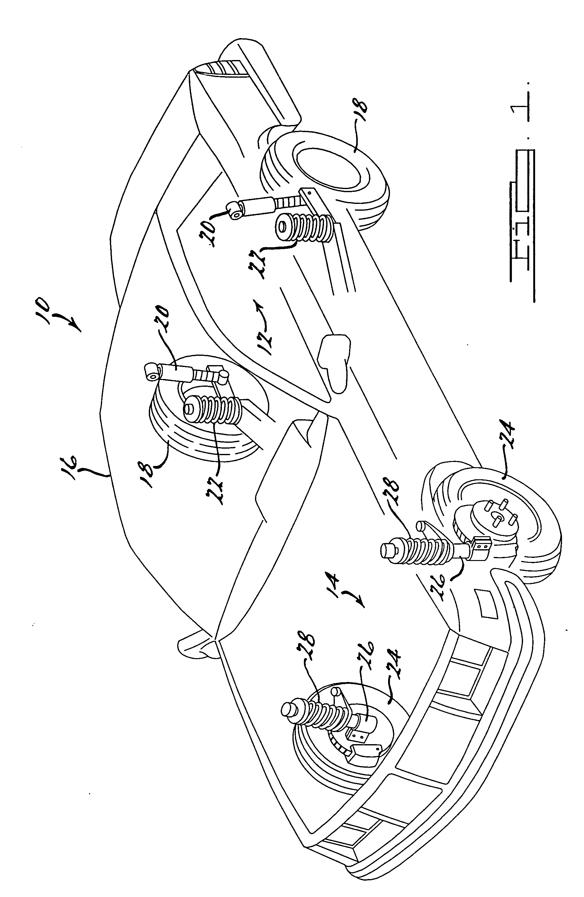
[0016] Referring now to the drawings in which like reference numerals designate like or corresponding parts throughout the several views. The following description of the preferred embodiment(s) is merely exemplary in nature and is in no way intended to limit the invention, its application, or uses. There is shown in FIG. 1, a vehicle incorporating shock absorbers which include the unique slip ring design in accordance with the present invention and which is designated generally by the reference numeral 10. Vehicle 10 includes a rear suspension system 12, a front suspension 14 and a body 16. Rear suspension system 12 includes a pair of rear suspension arms adapted to operatively support a pair of rear wheels 18. Each rear suspension arm is attached to body 16 by means of a shock absorber 20 and a helical coil spring 22. Similarly, front suspension system 14 includes a pair of suspension arms adapted to operatively support a pair of front wheels 24. Each suspension arm is attached to...


PUM


Abstract

A rod guide assembly for a shock absorber includes a seal assembly which is biased towards a sealing surface on the rod guide by a biasing member which is located between the seal assembly and the bearing which is assembled to the rod guide housing. The biasing of the seal assembly prohibits movement of the seal assembly during operation of the shock absorber. In addition, a wire circlip which radially biases the seal assembly can be included.

Description

FIELD OF THE INVENTION [0001] The present invention relates to shock absorbers. More particularly, the present invention relates to a unique slip ring which seals the interface between the piston rod and the rod guide. BACKGROUND OF THE INVENTION [0002] Shock absorbers are used in conjunction with automobile suspension systems and other vehicle suspension systems to absorb unwanted vibrations which occur during operation of the vehicle. To absorb this unwanted vibrations, shock absorbers are connected between the sprung mass (the body) and the unsprung mass (the suspension system) of the vehicle. A monotube shock absorber has a piston which is located within a pressure tube of the shock absorber and the piston is typically connected to the sprung mass of the vehicle using a piston rod. The pressure tube is typically connected to the unsprung mass of the vehicle and it is typically filled with hydraulic fluid. The piston includes valving systems which have the capability to limit the...

Claims


Application Information

Patent Timeline
IPC IPC(8): F16F9/32F16F9/36F16J15/56
CPCF16F9/3242F16F9/363F16J15/56
Inventor VANMECHELEN, PATRICKHOLIVIERS, DAVIDSCHURMANS, RUDI
Owner TENNECO AUTOMOTIVE OPERATING CO INC
Why Eureka
Try Eureka