Exhaust-driven turbo-charger central rotor device

A technology of exhaust gas turbine and supercharger, which is applied in the direction of machine/engine, engine sealing, engine components, etc., can solve the problems of unsatisfactory oil film formation effect, unsatisfactory sealing effect, and difficulty in supercharger sealing, and achieves convenient assembly. , The effect of enhancing sealing performance and reducing product cost

Inactive Publication Date: 2008-05-28
KANGYUE TECH
View PDF0 Cites 11 Cited by
  • Summary
  • Abstract
  • Description
  • Claims
  • Application Information

AI Technical Summary

Problems solved by technology

In particular, the turbocharger for vehicles works under the condition of a large range of operating conditions, so that the axial force of the supercharger is in a state of large fluctuations, and it is more difficult to solve the sealing of the supercharger
like figure 1 As shown, a current exhaust gas turbocharger core rotor device generally includes an intermediate casing 9, an impeller 2 installed at the end of the turbine shaft 10, a coupling disc 1, a shaft seal 3, a sealing ring 4, an oil baffle 5 and a stopper. The push sleeve 7 and the thrust bearing 6, the sealing ring 8 is arranged between the intermediate shell 9 and the connecting disc 1, the sealing ring 4 is arranged between the connecting disc 1 and the shaft seal 3, and the lubricating oil enters from the oil inlet of the intermediate shell 9, Enter the thrust bearing 6 along the straight oil passage in the middle shell 9, and be thrown out after both sides of the thrust bearing 6 are lubricated, and the lubricating oil in the thrust sleeve 7 is thrown out from the mating surface; After entering the floating bearing, it flows to the oil return port of the middle shell 9 after being lubricated, and is discharged by its own gravity. This kind of sealing structure has a large range of changes in the working conditions of the vehicle turbocharger, and the axial force of the supercharger is relatively large. When the ups and downs change state, part of the lubricating oil still enters the compressor area through the sealing ring 8 and the sealing ring 4, resulting in oil leakage from the supercharger, and the sealing effect is not ideal
The thrust bearing structure of this structure adopts the inner hole to supply oil, and the oil film formation effect is not ideal, which is easy to cause bearing wear

Method used


Image

  • Exhaust-driven turbo-charger central rotor device
  • Exhaust-driven turbo-charger central rotor device
  • Exhaust-driven turbo-charger central rotor device

Examples


Embodiment Construction

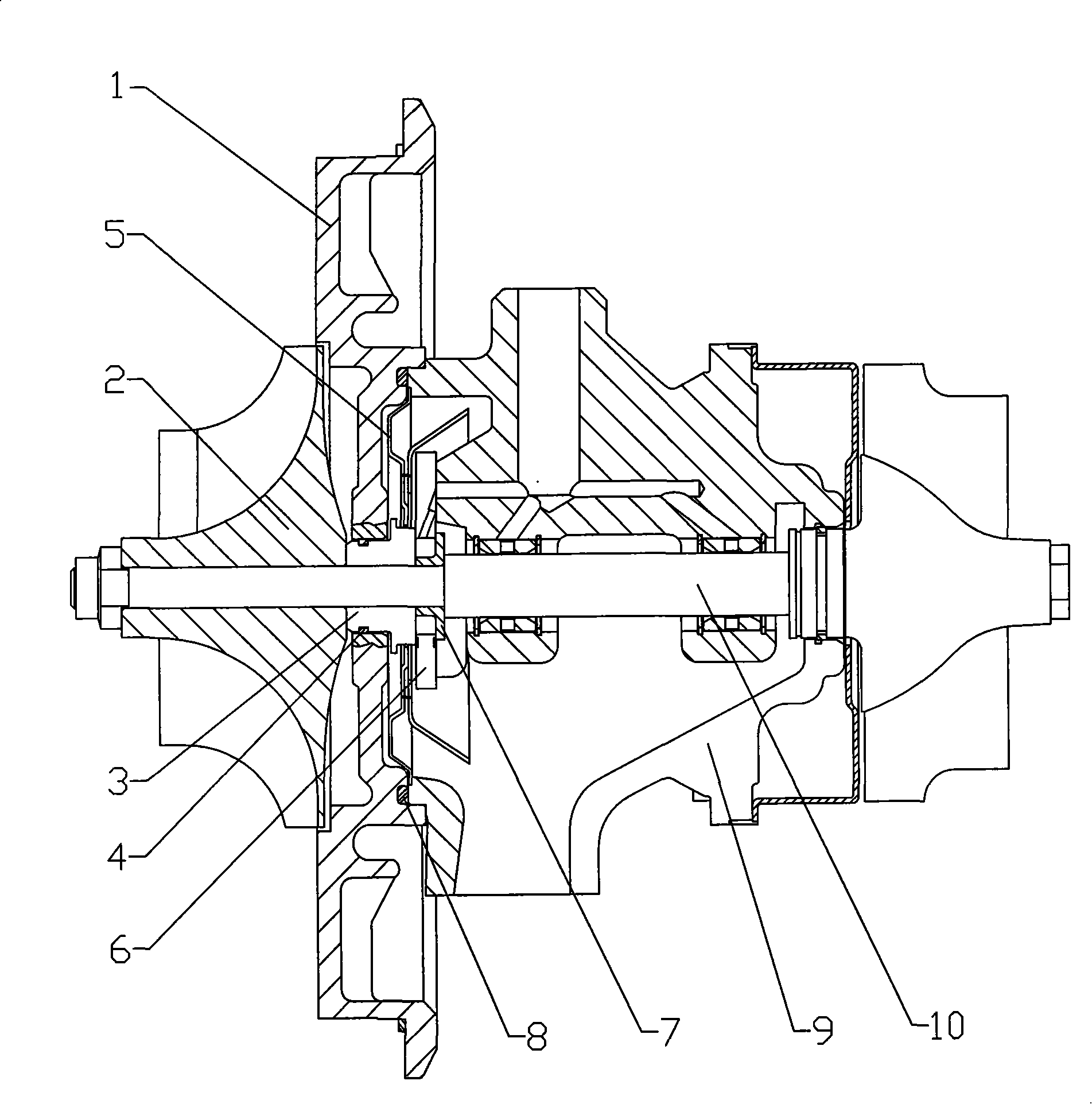
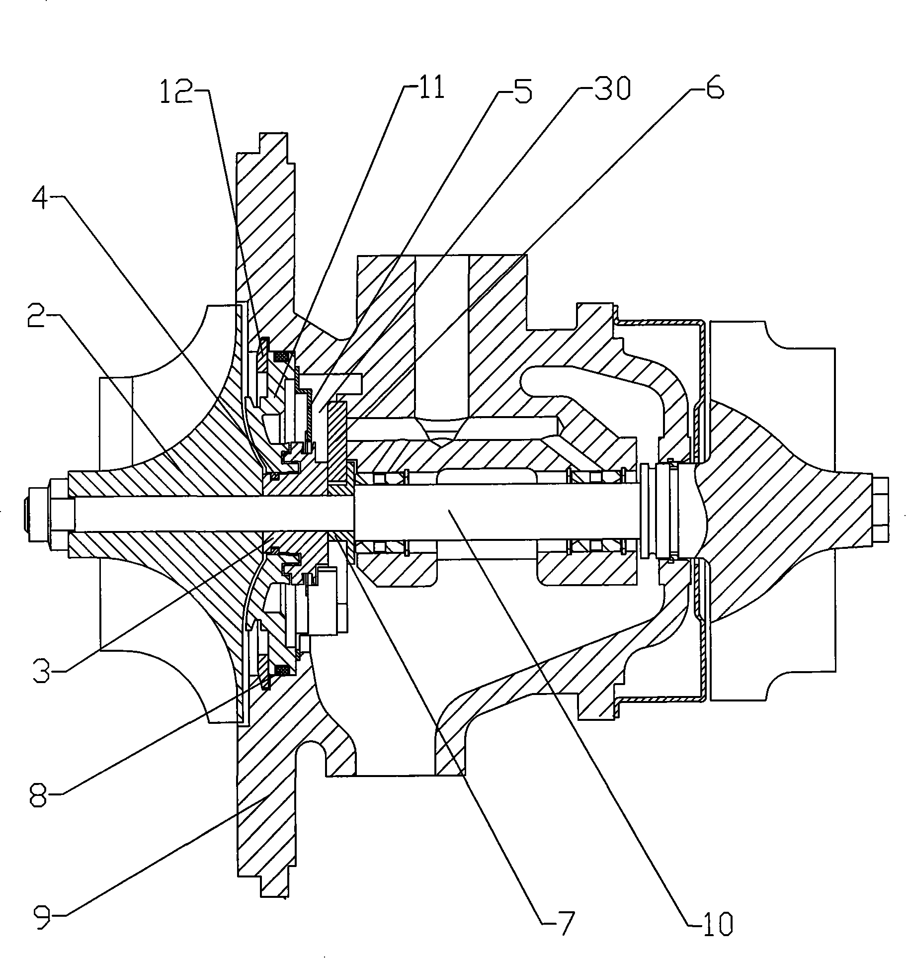
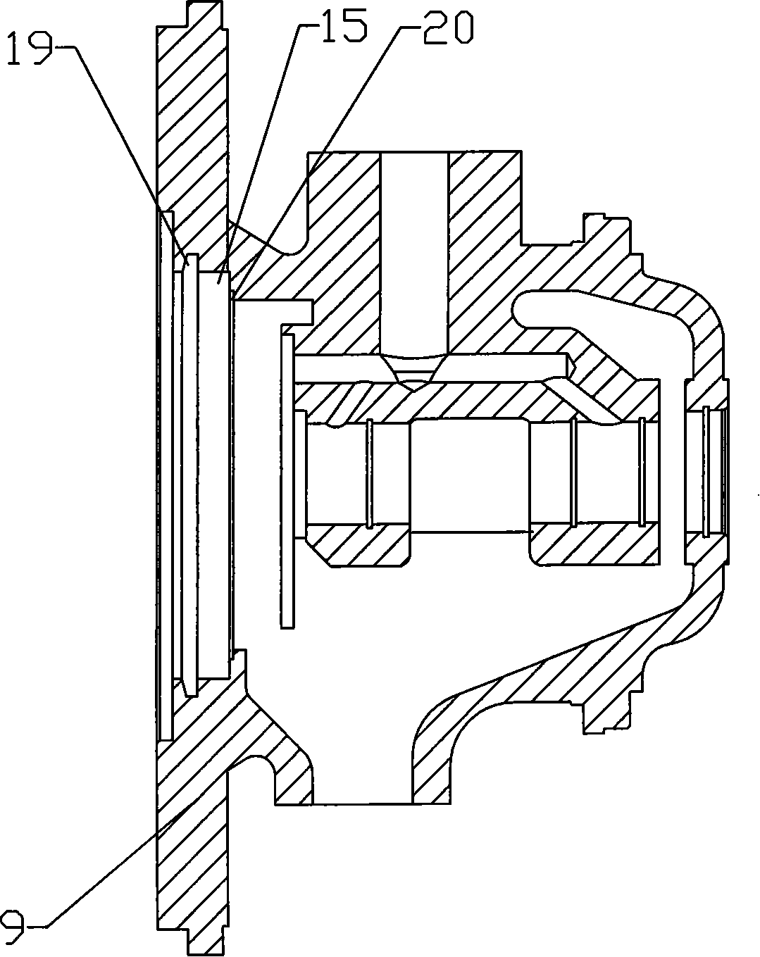
[0030] Examples such as figure 2 , image 3 As shown, a core rotor device of an exhaust gas turbocharger includes an intermediate shell 9, a thrust sleeve 7, a thrust bearing 6, an oil deflector 5, and a shaft seal 3. The thrust sleeve 7 is arranged on the turbine shaft 10, and The thrust bearing 6 is arranged on the thrust sleeve 7, the impeller 2 is arranged on the turbine shaft 10 at one end of the shaft seal 3, and the intermediate shell 9 at one end of the impeller 2 has a chamber 15, and a sealing ring sleeve 11 is arranged in the chamber 15, The inner wall of the chamber 15 is provided with an annular groove 19, and the annular groove 19 is provided with a circlip 12 for defining the position of the sealing ring housing 11. The circlip 12 is located on the side of the sealing ring housing 11 close to the impeller 2, The middle shell 9 in the chamber 15 is provided with a step 20, the step 20 is located on the side of the seal ring sleeve 11 away from the impeller 2, t...


PUM


Abstract

The invention discloses a kernel rotor device of an exhaust-gas turbocharger, comprising a middle casing, a thrust sleeve, a thrust bearing, an oil baffle, and a shaft gland, wherein a blade wheel is arranged on a turbine shaft on one end of the shaft gland, the middle casing on the one end of the blade wheel is provided with a chamber, a sealing ring sleeve base is arranged in the chamber, and the sealing ring sleeve base comprises a ring-shaped component which is sealed with the inner walls of the chamber and a lantern ring which is dynamically sealed by the shaft gland and is arranged on the turbine shaft. A ring-shaped connecting member is fixedly connected between the ring-shaped component and the lantern ring, one lateral side of the ring-shaped connecting member which faces the blade wheel is provided with an arc-shaped end face which is relative to the shape of the blade wheel. The original connection between a linking disk and the middle casing is changed into the connection of the middle casing and the sealing ring sleeve to remove the linking disk with large size, thereby avoiding deformation of the product. The original projection sealing is changed into notch sealing to enlarge the oil return space of the product, and the original screw pressing is changed into a circlip pressing, thereby providing conveniences for assembly, easily adopting an automatic assembly line, and reducing the cost of the product.

Description

technical field [0001] The invention relates to the core rotor assembly structure of a turbocharger for vehicles, in particular to an exhaust gas turbocharger that can be easily assembled, improves the sealing performance of the product, improves the dynamic performance of the rotor, and has good reliability The core rotor device. Background technique [0002] At present, the domestic automotive turbocharger has been rapidly improved in terms of performance, and has been able to replace imported products, but the reliability of the product restricts its competition with foreign brands. With the increase in product output and the wider application range , There are more and more failures of supercharger lubricating oil leakage and thrust bearing wear, especially in medium-sized trucks, heavy-duty trucks, and passenger cars. The sealing structure of the turbocharger is to prevent the lubricating oil in the middle shell from entering the flow part of the turbocharger, and prev...

Claims


Application Information

Patent Timeline
Patent Type & Authority Applications(China)
IPC IPC(8): F02B39/00F16J15/16
Inventor 王航郭锡禄郭伦海张在生张建国刘功利
Owner KANGYUE TECH
Why Eureka
Try Eureka