Electronic Circuit Experiment Board

a technology of electronic circuit and experiment board, which is applied in the direction of electrical apparatus casing/cabinet/drawer, circuit arrangement on insulating board, education models, etc., can solve the problems of increasing the experiment cost, reducing the teaching effect, and failure to experiment, and achieves good contact performance, high experimental efficiency, and strong visual impression

Inactive Publication Date: 2008-09-04
LI RONGCHANG
View PDF19 Cites 10 Cited by
  • Summary
  • Abstract
  • Description
  • Claims
  • Application Information

AI Technical Summary

Benefits of technology

[0025]The present invention use double sides binding posts which can be inserted whenever used, so it has the advantages of good contact performance, strong visual impressio

Problems solved by technology

According to experiment rules there is only one potential in the same point, while the different potential often appears because of the contact failure to different extent between four plugs and jacks in actual experiment, which leads to failure of experiments.
b. The design of large mesa structure increase the experiment cost and reduce the teaching effect, because students' practical chance in the based-on-team organization of experiment is insufficient, and the individuation creativity in the procedures and results of the experiment is difficult to exert.
c. Less link points for circuit connection can't support the complex experiment.
Special plug and wire cause high cost, and it's impossible to adjust the length of wire, which results in the confusion of wiring system and poor visual impression.
It has the arrangement of five jacks allocating in a row outside the same interconnect point of the wire, but one spring lamination inside the bread board, which results in the confusion of wiring system and poor visual impression.
Furthermore, the phenomenon of simultaneous contact failure of multi-point often appears in the process of inserting some straight or curved wiring with irregular round simultaneously in the same spring lamination because the elastic contact method of the connecting wiring still be used, which increases the difficulty of failure query, and lead to the interruption of experimental procedure finally.
In sum, the experimental apparatus for

Method used


Image

  • Electronic Circuit Experiment Board
  • Electronic Circuit Experiment Board
  • Electronic Circuit Experiment Board

Examples


Embodiment Construction

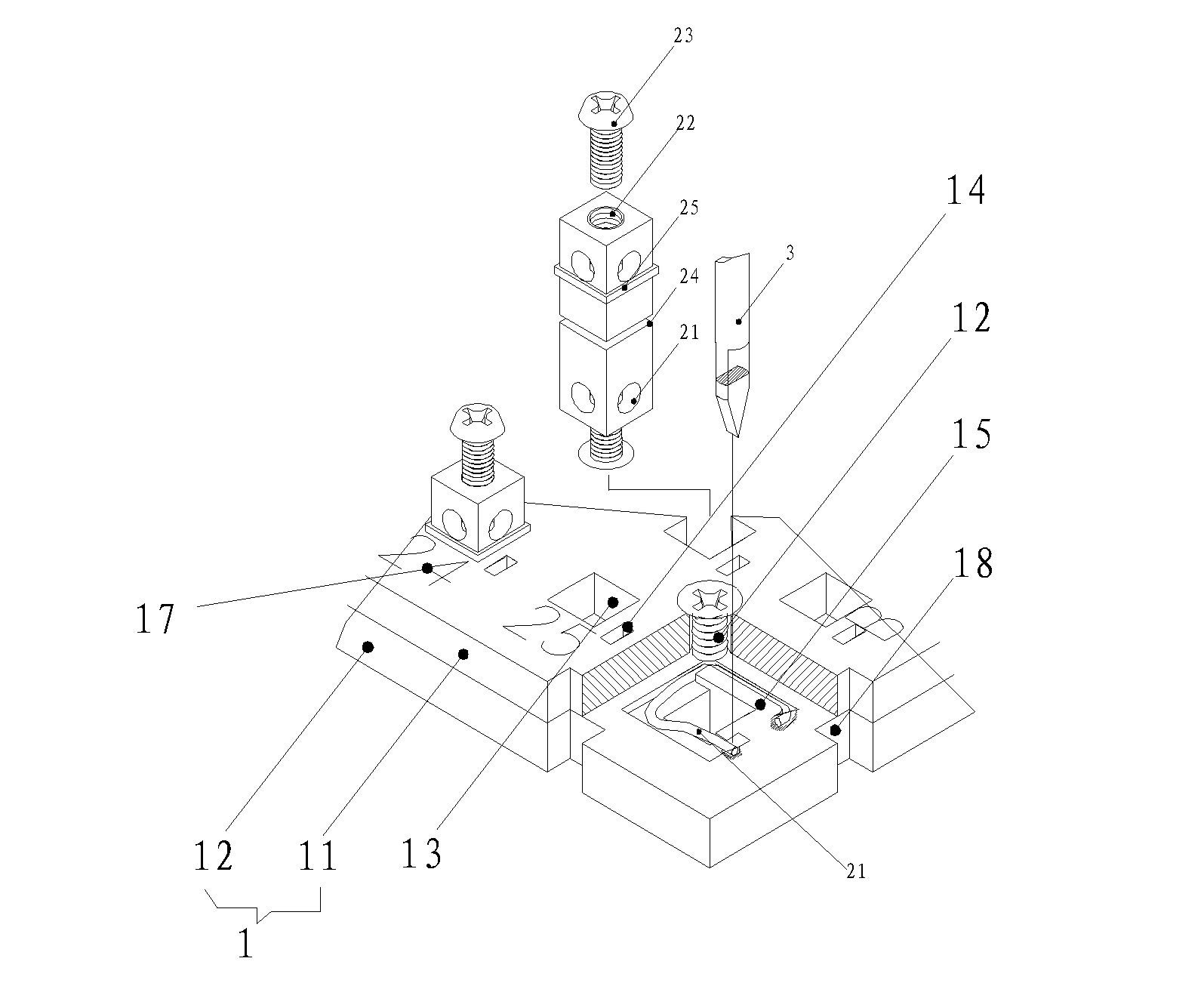
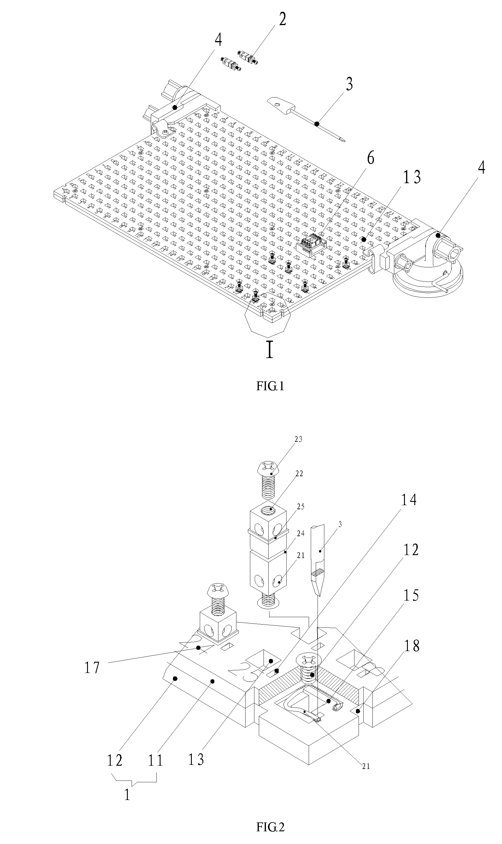
[0035]FIG. 1 and FIG. 2 are the references for the embodiment. The electronic circuit experiment board in the present invention is composed of an insulated base plate 1 and a plurality of binding posts 2, and the base plate 1 is divided into an upper plate 11 and a lower plate 12 which includes a plurality of binding post inserting holes 13 corresponding with the upper plate and the lower plate respectively. The binding posts 2 can be inserted into the binding post inserting holes 13. There are four binding holes 21 in the lateral face of the binding posts 2 which close to two ends. There are a screw hole 22 on the ends of the binding posts respectively, and the screw hole 22 are connected with the binding holes 21 that lies in the same side. The practical cross section of the binding posts in the binding holes get up to the mechanical strength demands. The binding posts 2 also includes a screw lever 23 cooperated with the screw hole 22. The conductor was inserted into the binding p...


PUM


Abstract

The present invention is an electronic circuit experiment board, which is composed of an insulated base plate, copper binding posts and a bracket and so on. The base plate is divided into an upper plate and a lower plate, which have binding post inserting holes and circlips. The binding posts can be inserted into the binding post inserting holes and then be fastened by the circlips. There are a binding hole and a screw hole on the ends of the binding posts respectively. The binding post also includes a screw lever cooperated with the screw hole, a positioning groove and a positioning ring. The experiment board has the advantages of good contact performance, convenient to use, high experimental efficiency, long service life and strong ability of splicing and dilatancy, arranging elements in double sides, and multilayer wiring in electronic circuit.

Description

BACKGROUND OF THE INVENTION[0001]1. Field of the Invention[0002]The present invention relates to an experimental apparatus for the electronic circuit, especially relates to the improvement of the electronic circuit experiment board.[0003]2. Description of the Prior Art[0004]The currently used experimental apparatus for the electronic circuit has lots of deficiency which is as follows:[0005]1. Experimental Table of Electronic Circuit[0006]The experimental table of the electronic circuit in laboratories has the following demerits.[0007]a. We use four plugs and jacks in experimental table to replace the intersection point of four lines in electrical circuit while using the plug wiring mode of elastic contact. According to experiment rules there is only one potential in the same point, while the different potential often appears because of the contact failure to different extent between four plugs and jacks in actual experiment, which leads to failure of experiments.[0008]b. The design ...

Claims


Application Information

Patent Timeline
IPC IPC(8): G09B23/18H05K7/10
CPCG09B23/183H05K7/08G09B23/185G09B23/18G09B25/00
Inventor LI, RONGCHANG
Owner LI RONGCHANG
Why Eureka
Try Eureka