Clear door vending machine

a vending machine and clear door technology, applied in the direction of instruments, coin-freed instruments, thin material handling, etc., can solve the problems of difficult to determine the availability of a product, messages often go unheeded, and the absence of a particular desired product, so as to achieve quick and easy control of the delivery of products

Active Publication Date: 2005-03-31
ROYAL VENDORS
View PDF49 Cites 60 Cited by
  • Summary
  • Abstract
  • Description
  • Claims
  • Application Information

AI Technical Summary

Benefits of technology

[0013] It is another object of the present invention to provide a product separation and selection tray system without the use of multiple, dedicated electronic devices or wiring exposed to the environment of a vending machine.
[0014] It is still another object of the present invention to provide quick and easy controlled delivery of products without agitation during delivery of the product or contact with the consumer until after the dispensing cycle is complete.
[0015] It is yet another object of the present invention to provide quick adjustment to a display tray of a clear panel vending machine to accommodate different sized packages.

Problems solved by technology

A common problem encountered during the use of these machines is the absence of a particular desired product.
In machines where the product is concealed behind a display panel, it is difficult to determine a product's availability.
Although visual displays may indicate “sold out” or “choose another product”, these messages often go unheeded.
This may be acceptable for dispensing snacks, but could have disastrous results for dispensing of glass encased liquids or carbonated beverages.
One problem encountered by the use of such a selection assembly is that the power and control wiring to a movable motor is difficult to route inside of a vending machine in a safe and controlled manner.
A problem encountered in the use of such a dispensing assembly is that many relatively expensive devices are required and often difficult wiring issues arise.
There is the potential for damage to the product, the mechanism or harm to the consumer.
The problem with this approach is the necessity to make, supply, insert and maintain these “loose” extra parts.

Method used


Image

  • Clear door vending machine
  • Clear door vending machine
  • Clear door vending machine

Examples


Embodiment Construction

[0059] In describing a preferred embodiment of the invention illustrated in the drawings, specific terminology will be resorted to for the sake of clarity. However, the invention is not intended to be limited to the specific terms so selected, and it is to be understood that each specific term includes all technical equivalents which operate in a similar manner to accomplish a similar purpose.

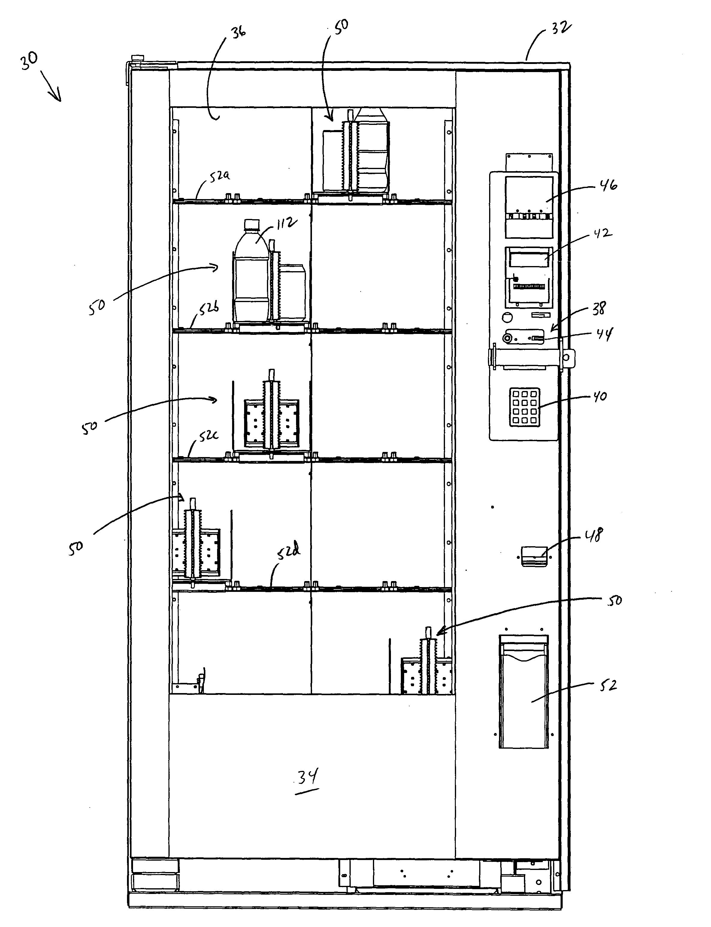
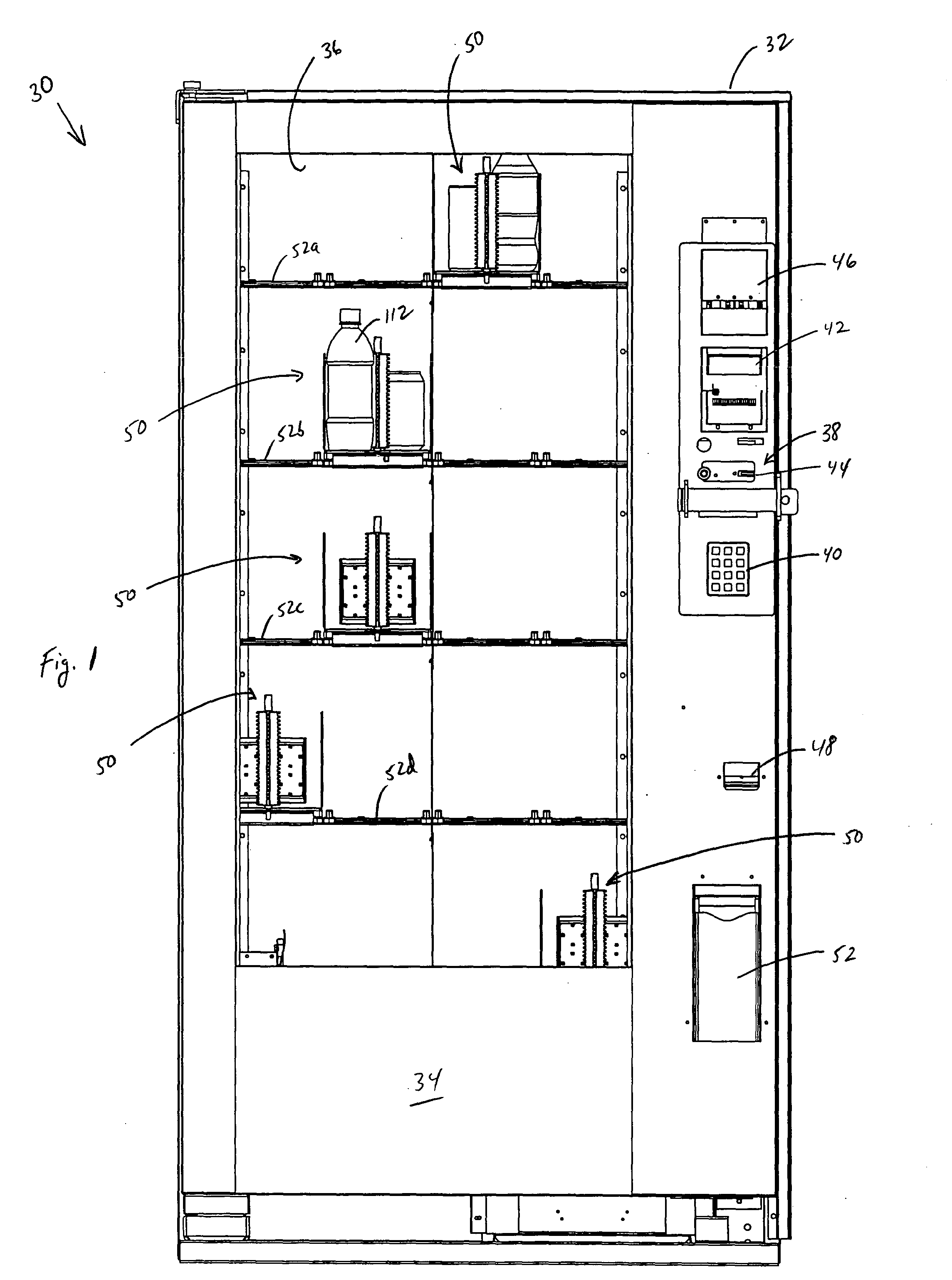
[0060] With reference to the drawings, in general, and to FIG. 1 in particular, a clear door vending machine embodying the teachings of the subject invention is generally designated as 30. With reference to its orientation in FIG. 1, the clear door vending machine includes a cabinet 32 with a front door 34 having a clear panel portion 36.

[0061] On the front face of the door 34 is located a control panel 38 having a digital keypad 40. Information entered into the digital keypad is displayed in display panel 42. In addition, the control panel 38 includes coin slot 44 and dollar bill receiver 46...


PUM


Abstract

Vending machine product is moved by the use of an “X-Y mechanism” having two stationary electronically controlled drive “motors”. These motors drive (directly or indirectly) tension elements (belt, chain, cable, etc.) that position horizontally and vertically sliding components. A separation and selection system uses a “rotator” to release a product from a tray and a “gate” to separate the products into two columns on the tray. A “lever” (centered by springs) mechanically links these components. Products move off the tray by a spring powered “slider” (one slider for each product column) on the tray. There is only one “rotator-gate-lever” mechanism per pair of product columns in each display tray. That is, when a “cup” engages the “lever” moving to the right, a product from the left side of the display tray is pushed into the “cup” and vice versa. Adjustable side walls in each tray accommodate different sized packages. The delivery mechanism uses the “cup” for transport. A lower surface of the cup engages a sliding “door” to a balanced delivery “port” for delivery of product from the cup to the port. Delivery is made from the cup to the port simultaneously with the opening of the door.

Description

FIELD OF THE INVENTION [0001] The present invention relates to a clear door vending machine having a product separation and selection tray system, a fixed motor X-Y axis product acquisition and transport system and a controlled delivery of product system. BACKGROUND OF THE INVENTION [0002] Although the 1880s are usually considered the dawn of the vending machine era, vending machines have existed for a couple of thousand years. The earliest reference to a vending machine was made by a Greek mathematician, who described and illustrated a coin-operated device used for vending sacrificial water in Egyptian temples. The machine was completely automatic, set in operation by insertion of a five-drachma coin. [0003] More recent times have seen a vast proliferation of vending machines for all types and sizes of products. These machines have become ubiquitous on the American landscape, primarily dispensing snacks and drinks. [0004] A common problem encountered during the use of these machine...

Claims


Application Information

Patent Timeline
Patent Type & Authority Applications(United States)
IPC IPC(8): G07F11/16G07F11/42G07F11/60
CPCG07F11/16G07F11/60G07F11/42G07F11/165G07F11/1653G07F11/163
Inventor HOLDWAY, JOHN BARRETTHALTERMAN, BRIANRING, MIKE
Owner ROYAL VENDORS
Why Eureka
Try Eureka