
Wear ring assembly for centrifugal rock crusher turntables

Inactive Publication Date: 2005-03-31
ROSE BRETT M
View PDF3 Cites 2 Cited by
  • Summary
  • Abstract
  • Description
  • Claims
  • Application Information

AI Technical Summary

Benefits of technology

[0005] In its basic form, the wear ring assembly of this invention includes a base ring member having a hardness of 600 to 800 Brinell and a chrome content of 12-30% and a carbon content of 2.6-3.3% by weight, and an overlying bolt ring formed of softer steel exhibiting high strength and resistance to cracking and breaking.
[0008] Still another objective of this invention is to provide a wear ring assembly of the class described in which a hardened wear ring is coupled with an overlying bolt ring of softer steel which protects against separation of hard fragments if the wear ring should break, and thereby minimize damage to the rock crusher.
[0010] A still further objective of this invention is the provision of a wear ring assembly of simplified construction for economical manufacture and repair.

Problems solved by technology

While this material suffers the disadvantage of a comparatively short wear life, it is less susceptible to the occurrence of shattering and breaking under these operating conditions than wear rings made of harder and more brittle material that has greater wear lives.
The extensive damage that results to the rock crusher apparatus when a broken fragment of a hardened wear ring member is thrown off at high speed, is considered generally to outweight the shorter wear life of the softer material ring members that are less susceptible to breaking and cracking under operation.

Method used


Image

  • Wear ring assembly for centrifugal rock crusher turntables
  • Wear ring assembly for centrifugal rock crusher turntables
  • Wear ring assembly for centrifugal rock crusher turntables

Examples


first embodiment

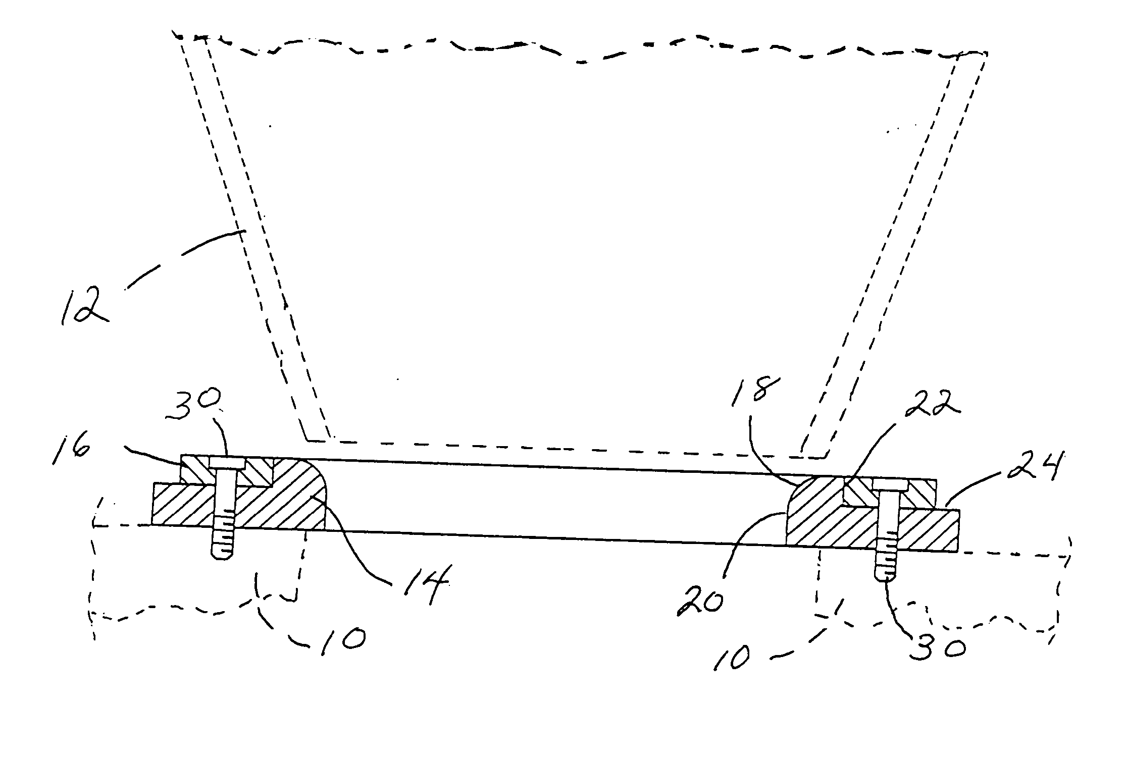
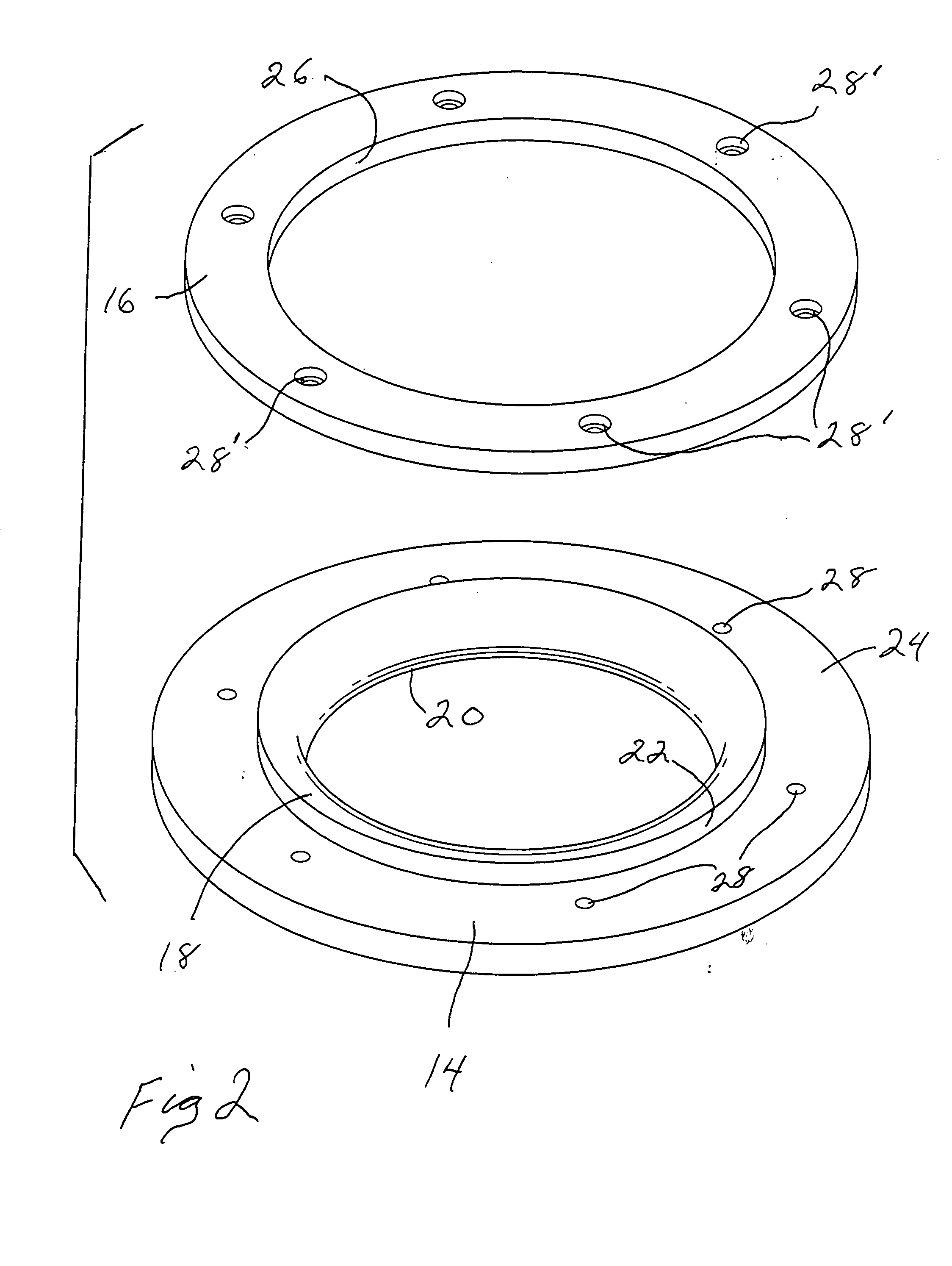
[0020]FIGS. 1 and 2 illustrate wear ring assembly embodying the features of this invention. FIG. 1 also shows the wear ring assembly supported on a plurality of underlying impeller units 10, 10 of a centrifugal rock crusher. The wear ring assembly also is shown in positioned position beneath a feed hopper 12 of a centrifugal rock crusher, the feed hopper being shown in broken lines. FIG. 1 illustrates a sectional view through the wear ring assembly and FIG. 2 provides a perspective view of the component parts of the wear ring assembly.

[0021] As best shown in FIG. 2, the wear ring assembly of this embodiment comprises two interengaging ring members: a base, wear surface ring member 14 and an overlying bolt ring member 16. Those skilled in the art will recognize that the outer diameter of the wear ring base member 14 is dimensioned to correspond with the diameter of the turntable of a centrifugal rock crusher and also with the impeller system 10 to which the wear ring is mounted.

[002...

third embodiment

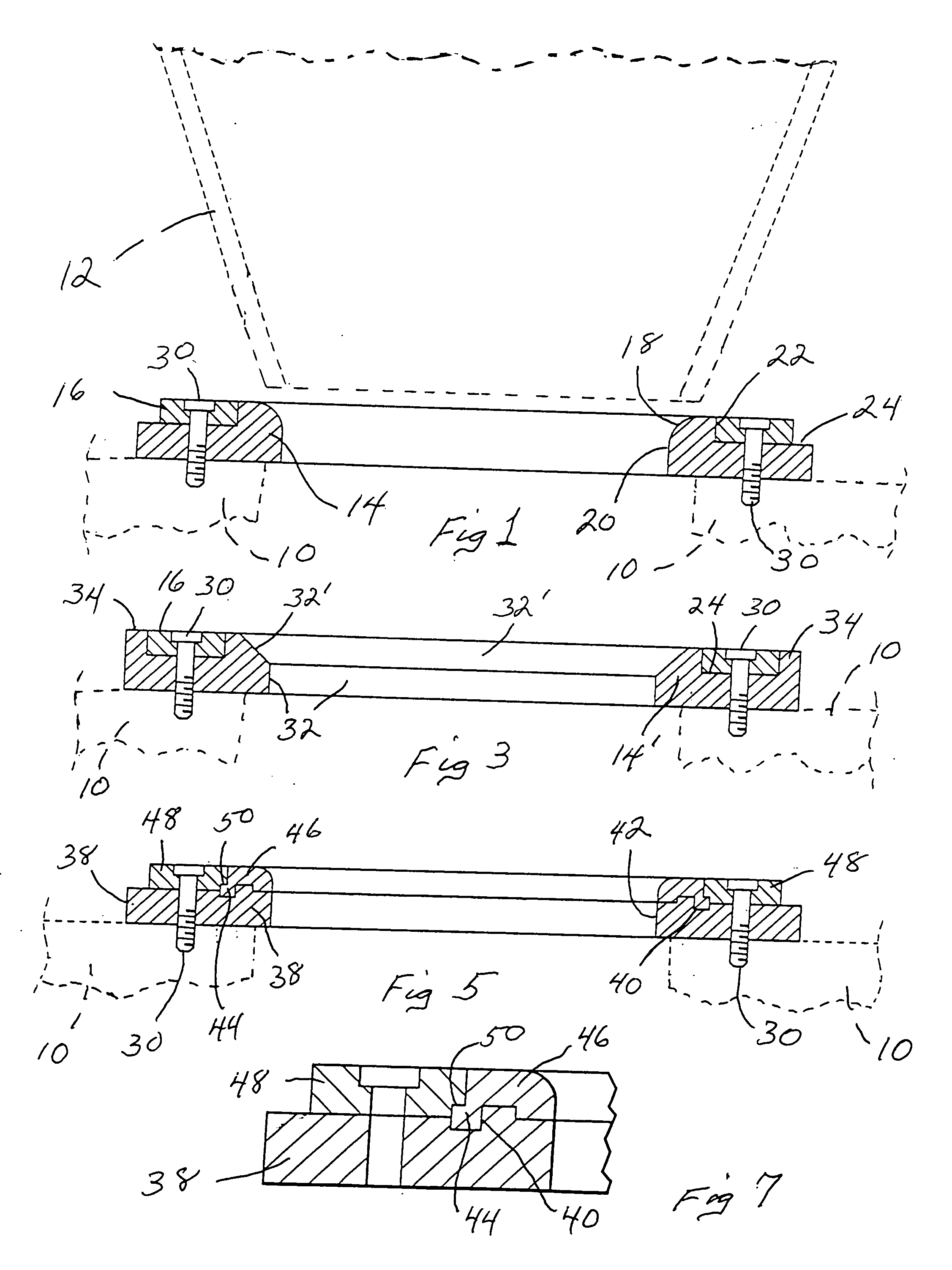
[0027]FIGS. 5, 6 and 7 illustrate the wear ring assembly of this invention which utilizes a segmented base wear ring configuration and a separate, central, annular wear surface ring member and bolt ring member for securing the assembly together. In this embodiment, the wear ring member 36 (FIG. 6) is formed of a plurality of separate, identical segments 38. Each segment is configured with a locking groove 40 (FIG. 7) that combines with the other segments of the ring to form an annular seating ring encircling the inner opening 42 of the ring member for mating, seated interengagement of the corresponding annular tab 44 on the central annular wear ring member 46 which overlies the segmented annular ring member 36. An overlying bolt ring member 48 is configured with an inner annular notch 50 arranged to overly and capture the tab 44 when the bolt ring is placed into overlying position on the base ring member 36. Mounting bolt bores 28, 28″ are provided as described in connection with th...


PUM


Abstract

This invention is a wear ring assembly for centrifugal rock crushers, and it comprises an annular wear ring member of hardened, brittle metal preferably having a Brinell hardness number of 600-800, a chrome content of 12-30% by weight and a carbon content of 2.6-3.3% by weight. The annular wear ring member forms an infeed opening for delivery of rock to the rock crusher. A bolt ring member of softer metal of high strength and resistance to breaking is secured over the wear ring member to protect the rock crusher from damage by high velocity fragments of hard, brittle wear ring material which would otherwise occur when the wear ring member would fracture under the impact force of large pieces of rock introduced into the rock crusher. In one embodiment the wear ring member is formed as a plurality of segments which are secured together as an annular ring by an overlying bolt ring which also secures a second annular wear ring member forming the upper portion of the annular opening.

Description

[0001] This application claims benefit of Provisional application Ser. No. 60 / 506,248, Filed 25 Sep. 2003.BACKGROUND OF THE INVENTION [0002] This invention relates to rock crushers, and more particularly to a novel wear ring assembly for centrifugal rock crushers. [0003] In order to assure that all of the incoming rock material is thrown outwardly into impact with the anvil assembly of a centrifugal rock crusher, a wear ring cap member is typically secured to the upper side of the impeller assembly of a rock crusher turntable to form an overlying top cap cover member with a central opening therethrough for passage of rock onto the turntable and into the impeller spaces between the underlying turntable and overlying top cap wear ring member. Heretofore, wear rings have been provided as simple disc-like metal plates provided with annular bolt holes therethrough positioned to correspond with threaded bores in a plurality of impeller units secured to the turntable. [0004] Typically, wea...

Claims


Application Information

Patent Timeline
IPC IPC(8): B02C13/18
CPCB02C13/1807
Inventor ROSE, BRETT M.
Owner ROSE BRETT M
Learn More