
Powder green compact, sintered compact and processes for producing them

a technology of sintered compacts and green compacts, which is applied in the direction of special fuel injection apparatuses, machines/engines, synthetic resin layered products, etc., can solve the problems of low mechanical strength, easy cracking of intricate green compacts, and difficulty in producing complex products by conventional powder metallurgy processes. , to achieve the effect of high mechanical strength, high mechanical strength and resistance to cracks or breakag

Inactive Publication Date: 2013-09-03
HIROSHIMA UNIVERSITY +1
View PDF8 Cites 1 Cited by
  • Summary
  • Abstract
  • Description
  • Claims
  • Application Information

AI Technical Summary

Benefits of technology

[0033]The powder green compacts of the invention have high mechanical strength and are resistant to cracks or breakage even when formed in a highly complicated shape. The green compacts can be mechanically processed into a highly complicated shape. The high mechanical strength permits easy release of the powder green compacts from the mold.
[0034]The sintered compacts of the invention can be formed with a highly complicated inner structure and shape and have high strength, finding use in various industrial parts including machinery parts.
[0035]The processes for producing powder green compacts according to the invention can produce powder green compacts that have high mechanical strength and are resistant to cracks or breakage even when formed with a highly complicated inner structure and shape, or that can be mechanically processed into a highly complicated inner structure and shape.
[0036]The processes for producing sintered compacts of the invention can produce sintered compacts having high strength and highly complicated inner structure and shape. The present invention solves the conventional cost problems with products such as diesel engine fuel injection nozzles having a large number of fine injection holes. According to the invention, such products can be produced easily at low cost and with high precision.

Problems solved by technology

However, it has been difficult to produce products with complicated shapes by conventional powder metallurgy processes.
The powder green compacts prepared by the conventional processes tend to have internal pores and consequent low mechanical strength, and thus intricately-shaped green compacts are easily broken.
Because of the low mechanical strength of the green compacts, the mechanical processing of compacts with a simple shape into a complicated shape is difficult.
Because the high-speed centrifugal compaction processes allow for high mechanical strength of compacts, the compacts can be formed into a relatively complicated configuration.
When the compacts are designed with a highly complicated shape, however, even the high-speed centrifugal compaction processes result in cracks or the like at heavily irregular portions.
Even the process disclosed in JP-A-2005-48230 cannot prevent the occurrence of cracks or the like.
Further, damages are often caused when the compacts prepared by the high-speed centrifugal compaction processes are machine processed into a highly complicated shape.
Therefore, the high-speed centrifugal compaction processes are not suited for the production of highly intricate compacts such as precursors of diesel engine fuel injection nozzles.
As a result, it has been difficult to produce sintered compacts having a very complicated shape by the powder metallurgy processes.Patent Document 1: JP-A-2005-48230

Method used


Image

  • Powder green compact, sintered compact and processes for producing them
  • Powder green compact, sintered compact and processes for producing them
  • Powder green compact, sintered compact and processes for producing them

Examples


example 1

[0084]A compact as a diesel engine fuel injection nozzle precursor, and a diesel engine fuel injection nozzle were fabricated as described below.

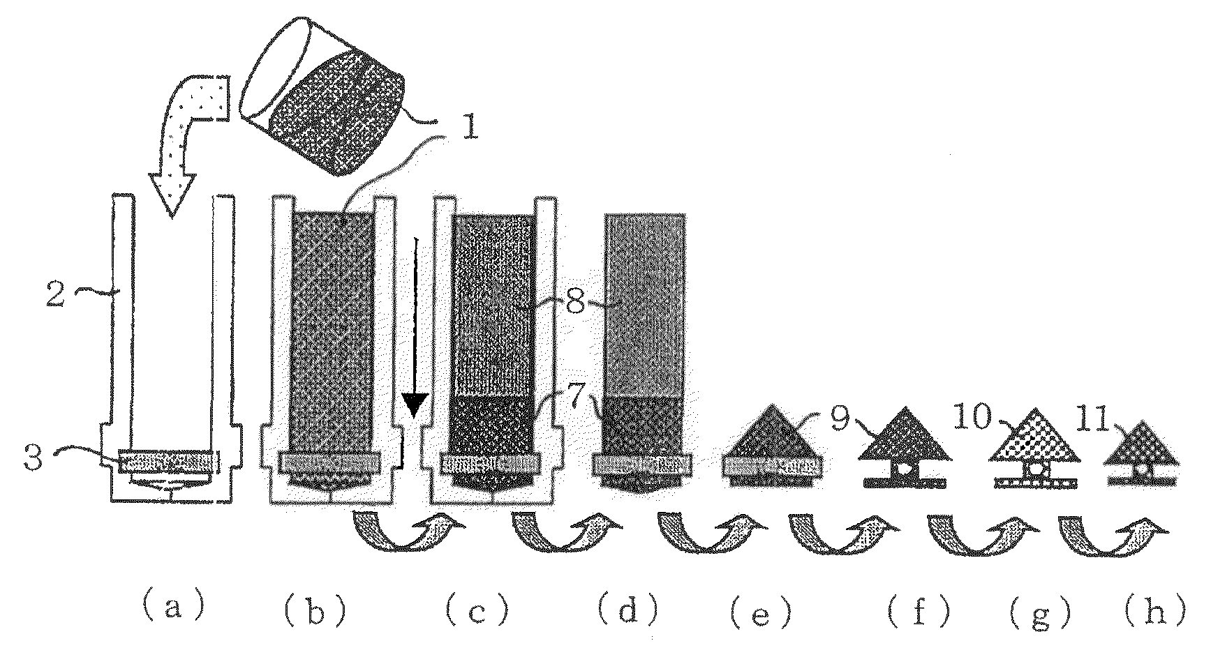
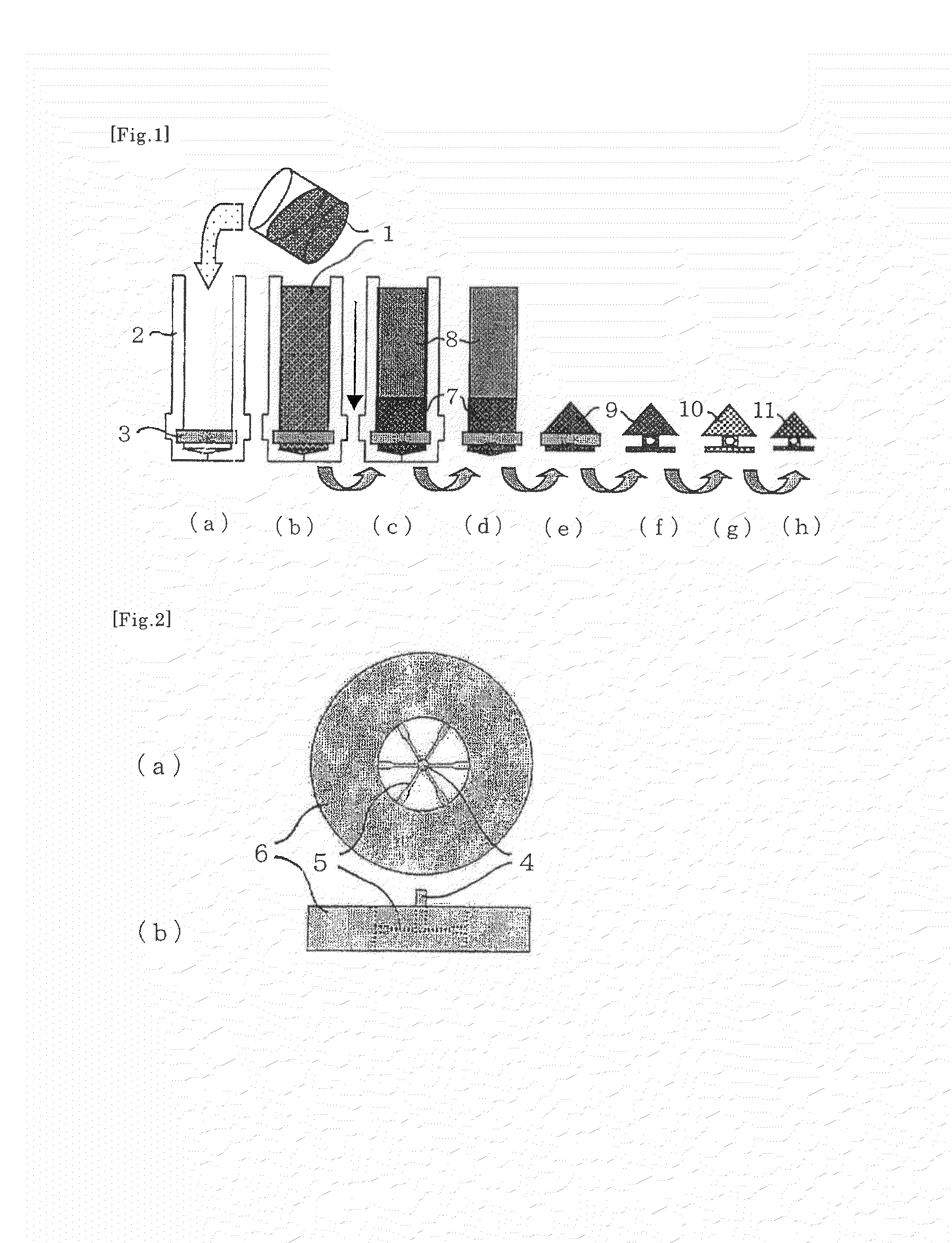
[0085]A split mold consisting of two aluminum cavities was provided which was capable of forming a cylindrical compact with an inner diameter of 8 mm. An acrylic resin core similar to the core 3 shown in FIG. 2 was interposed between the cavities, and the two cavities were combined. The core had branches with a diameter of 0.2 mm.

[0086]5 g of a styrene monomer was mixed with 5 g of a cold-curing epoxy acrylate resin. The mixture liquid was mixed with 20 g of cold-forming steel SKD 11 having a particle diameter of 4 μm (manufactured by EPSON ATMIX CORPORATION). The resultant mixture liquid was combined with 0.8 g of a polyoxyethylene distyrene and 0.3 g of PERCURE VL. The mixture was stirred sufficiently to give a slip.

[0087]The slip was injected into the mold. The mold was set in a high-speed cooling centrifuge with a rotor radius of 98 mm ...

example 2

[0094]A diesel engine fuel injection nozzle was prepared and a fuel injection test was carried out as described below.

(Production of Sintered Compact)

[0095]A split mold consisting of two aluminum cavities was provided which was capable of forming a cylindrical compact with an inner diameter of 18 mm. An acrylic resin core similar to the core 3 shown in FIG. 2 was interposed between the cavities, and the two cavities were combined. The core had branches with a diameter of 100 μm.

[0096]5 g of a styrene monomer was mixed with 5 g of a cold-curing epoxy acrylate resin. The mixture liquid was mixed with 20 g of cold-forming steel SKD 11 having a particle diameter of 4 μm (manufactured by EPSON ATMIX CORPORATION). The resultant mixture liquid was combined with 0.8 g of a polyoxyethylene distyrene and 0.15 g of PERCURE VL. The mixture was stirred sufficiently to give a slip.

[0097]The slip was injected into the mold. The mold was set in a high-speed cooling centrifuge with a rotor radius of...


PUM

PropertyMeasurementUnit
diameteraaaaaaaaaa
diameteraaaaaaaaaa
temperatureaaaaaaaaaa

Abstract

A process for producing powder green compacts includes centrifugally compacting a slip containing a material powder, a binder resin and a dispersion medium in a mold, into a compact containing the material powder and the binder resin. A process for producing sintered compacts includes sintering the green compact. A powder green compact contains a material powder and a binder resin, the binder resin being present between particles of the material powder and binding the material particles. A sintered compact is obtained by sintering the green compact.

Description

[0001]This application is a 371 of PCT / JP08 / 55896 filed Mar. 27, 2008. Priority to Japan 2007-121635 filed May 2, 2007, is claimed.FIELD OF THE INVENTION[0002]The present invention relates to powder green compacts, sintered compacts, and processes for producing these compacts. In more detail, the invention relates to powder green compacts containing binder resins and sintered compacts therefrom, and the whole process for producing these compacts.BACKGROUND OF THE INVENTION[0003]Powder metallurgy is a technique in which powder, which is usually metal, is compacted in a mold into a powder green compact and the green compact is sintered at temperatures slightly lower than the melting temperature of the whole compact, thereby producing a sintered compact, that is, a product. The technique can manufacture a large number of products of identical shape inexpensively, and is therefore widely used in the production of automobile parts, machinery parts, magnetic materials and cutting tools.[0...

Claims


Application Information

Patent Timeline
Patent Type & Authority Patents(United States)
IPC IPC(8): B22F1/00B22F1/107
CPCB22F1/0074B22F3/1291B22F3/22B22F2998/10B22F2999/00F02B23/0669F02M61/168F02M2200/8046B22F3/162B22F3/1021B22F2202/17Y10T428/31681Y10T428/31529Y10T428/31703B22F1/107
Inventor SUZUKI, HIROYUKISHIMOITANI, YOSHINOBU
Owner HIROSHIMA UNIVERSITY
Learn More