Plasma display panel having improved efficiency

Inactive Publication Date: 2005-03-31
SAMSUNG SDI CO LTD
View PDF9 Cites 5 Cited by
  • Summary
  • Abstract
  • Description
  • Claims
  • Application Information

AI Technical Summary

Benefits of technology

[0020] The invention is directed to a plasma display panel (PDP), having high definition due to a reduced pixel size, as well as a lowered discharge initiation voltage and an improved efficiency of discharge.

Problems solved by technology

Crisp images are the hallmark of CRT televisions, but such devices are bulky because a wide screen requires a correspondingly long electron gun in order for the electron stream to reach all parts of the screen.
However, when a conventional gap G1 is formed at predetermined intervals as shown in FIG. 2, initiation of the sustain discharge occurs locally, causing the spread of the discharge to be non-uniformly distributed.
This unnecessary portion decreases the discharge efficiency of a discharge cell, and also decreases luminance by covering (e.g., blocking) an area of the discharge cell.

Method used


Image

  • Plasma display panel having improved efficiency
  • Plasma display panel having improved efficiency
  • Plasma display panel having improved efficiency

Examples


Embodiment Construction

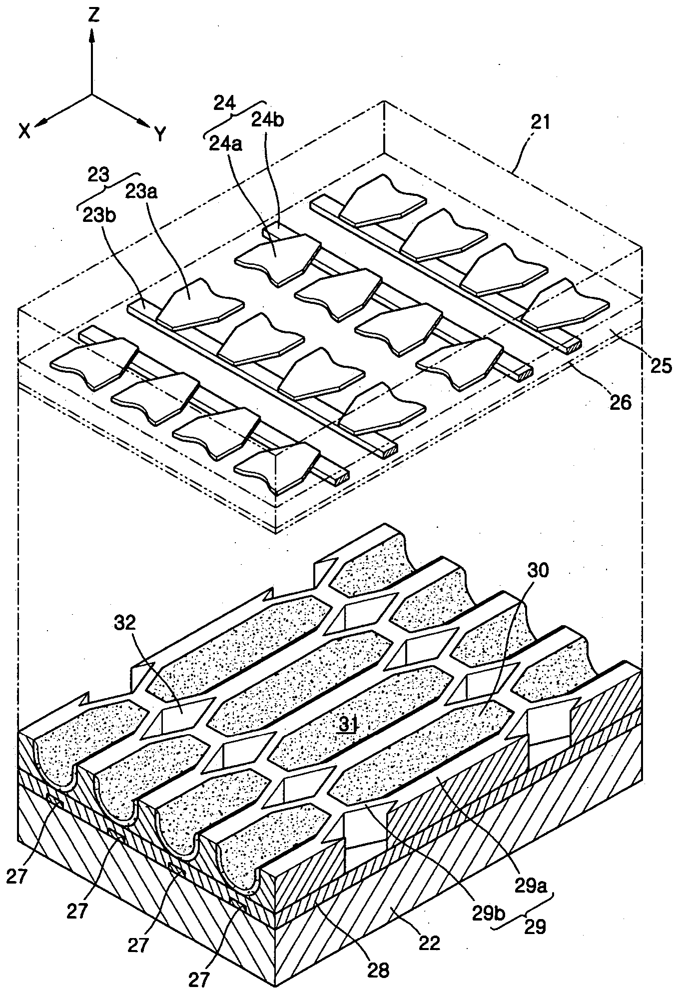
[0034] Embodiments of the present invention offer an improved PDP that offers a lowered discharge initiation voltage as well as an improved efficiency of discharge. The PDP may satisfy the equation 180≦(A+B)+P×0.1≦240 in which A is a distance between opposite recessed portion of a pair of a first electrode and a second electrode; B is a distance between opposite projection portions of the pair of the first electrode and the second electrode; and P is a gas pressure of a discharge gas contained in the discharge space. In another embodiment a gas pressure of a gas trapped in a discharge space (e.g., “cell” or “discharge cell”) may be over 450 Torr. Additionally, the PDP may include a first substrate having formed therein a plurity of pairs of first and second electrodes. Each opposing end of the first electrode and the second electrode may include a recessed portion and a projection portion such that a gap interposed between the electrodes' opposing end portions has different widths. ...


PUM


Abstract

Embodiments of the present invention offer an improved PDP that offers a lowered discharge initiation voltage as well as improved efficiency of discharge. The PDP may satisfy the equation 180≦(A+B)+P×0.1≦240 in which A is a distance between opposite recessed portion of a pair of a first electrode and a second electrode; it is a distance between opposite projection portions of the pair of the first electrode and the second electrode, and P is a gas pressure of a discharge gas contained in the discharge space. In another embodiment a gas pressure of a gas trapped in a discharge space (e.g., “cell” or “discharge cell”) may be over 450 Torr. Additionally, each opposing end of the first electrode and the second electrode may include a recessed portion and a projection portion such that a gap interposed between the opposing end portions varies in width.

Description

BACKGROUND OF THE INVENTION [0001] This application claims priority of Korean Patent Application No. 2003-56428, filed on Aug. 14, 2003, in the Korean Intellectual Property Office, of which is herein incorporated by reference. [0002] 1. Field of the Invention [0003] The present invention relates to a plasma display panel (PDP), and more particularly, to a PDP having high discharge efficiency. [0004] 2. Description of the Related Art [0005] For many years, television screens have been manufactured using cathode-ray-tube (CRT) technology. In a CRT television, an electron gun shoots a beam of electrons inside a glass tube. The electrons impact phosphor atoms at the screen (e.g., the wide end of the tube). In response, the excited phosphor atoms light up. Illuminating various areas of the phosphor coating with different colors at particular intensities produces the television image. Crisp images are the hallmark of CRT televisions, but such devices are bulky because a wide screen requir...

Claims


Application Information

Patent Timeline
IPC IPC(8): H01J11/22H01J11/24H01J11/34H01J11/36H01J11/50
CPCH01J11/12H01J2211/365H01J2211/245H01J11/24H01J17/22H01J11/50
Inventor WOO, SEOK-GYUNKIM, SE-JONG
Owner SAMSUNG SDI CO LTD
Why Eureka
Try Eureka