Optical module, optical fiber laser device and image display device

a technology of optical fiber laser and optical fiber, applied in the direction of optical elements, semiconductor lasers, instruments, etc., can solve the problems of difficult to achieve this, difficult to condense the beam into a very fine spot, and the beam cannot be correctly optically coupled to an optical fiber

Inactive Publication Date: 2005-03-31
KK TOSHIBA
View PDF0 Cites 40 Cited by
  • Summary
  • Abstract
  • Description
  • Claims
  • Application Information

AI Technical Summary

Benefits of technology

[0032] wherein at least one of the plurality of laser devices comprises a first optical element configured to collimate laser beams exited from a plurality of laser emitting sections in an array which are arranged along an active layer, a second optical element configured to enable those collimated beams which are oriented along the active layer to be arrayed perpendicular to the active layer, a third optical element configured to effect an image conversion in a direction along the activ

Problems solved by technology

However, since the semiconductor laser is not symmetrical in the widths of their emitters between a fast-axis perpendicular to an active layer and a slow-axis horizontal to the active layer and, further, the broadening of the laser beam is also not symmetrical, it is difficult to condense the beam into a very fine spo

Method used


Image

  • Optical module, optical fiber laser device and image display device
  • Optical module, optical fiber laser device and image display device
  • Optical module, optical fiber laser device and image display device

Examples


Embodiment Construction

[0044] With reference to the drawing, an explanation will be made in more detail below about the embodiments of the present invention.

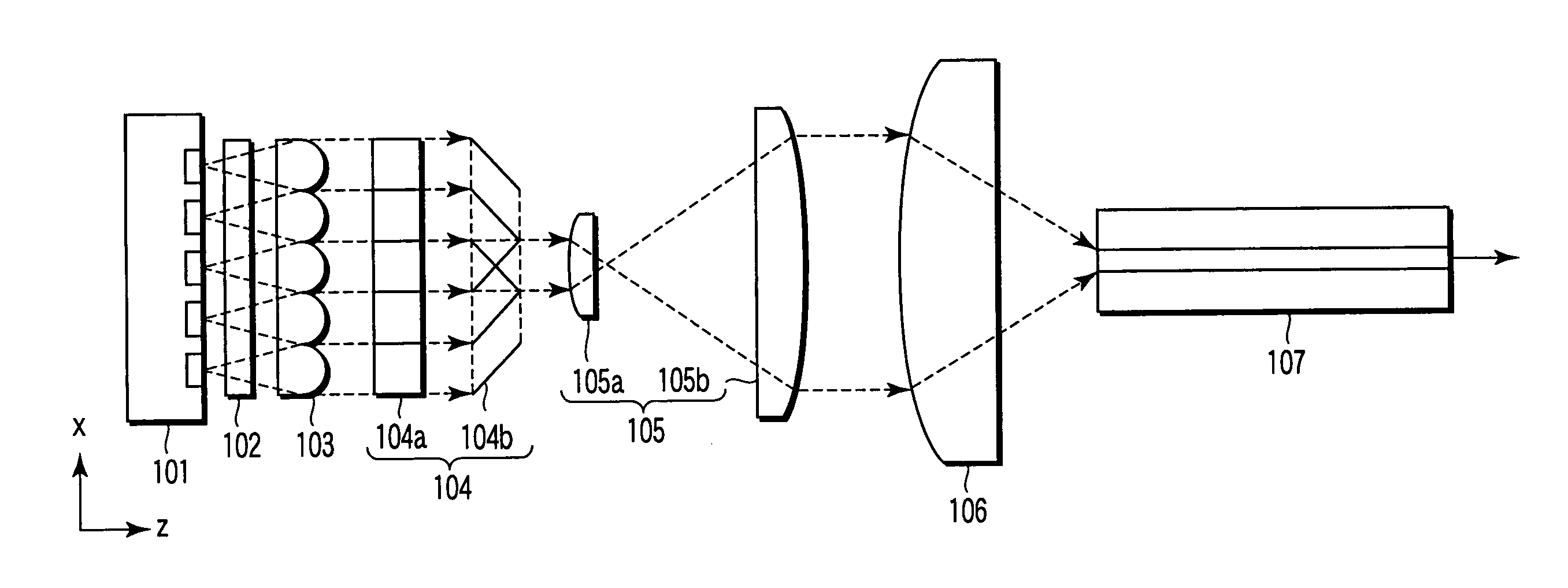
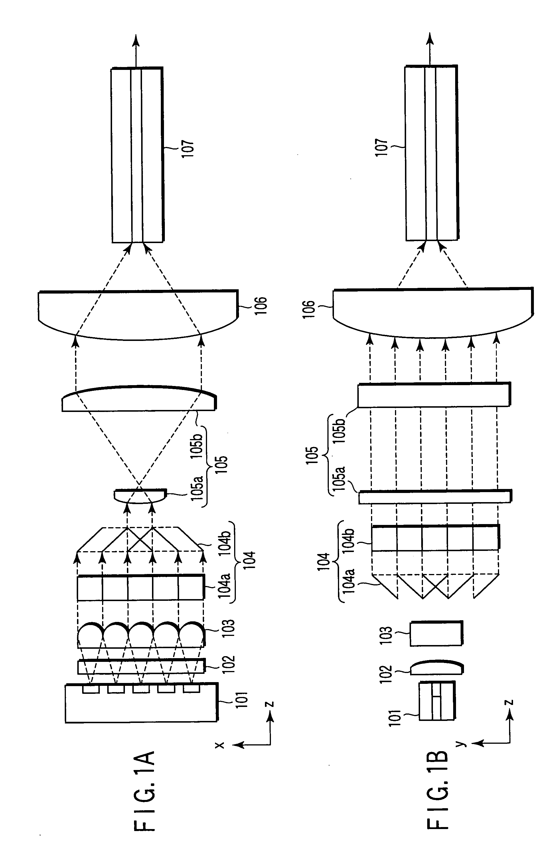
[0045]FIGS. 1A and 1B show one example of an optical module to which the embodiment of the present invention is applied, FIG. 1A being a y-z plan view and FIG. 1B an x-z plan view.

[0046] The optical module 100 of the present invention includes a monolithic semiconductor laser array 101 having an active layer with a plurality of light emitting points arranged therein, a collimating cylindrical lens 102 for collimating fast axis (that is, y-axis) components, a collimating cylindrical lens array 103 for collimating slow-axis (that is, x-axis) components, a beam shaping prism 104 (first and second beam shaping prisms 104a and 104b), a beam expander (first and second cylindrical lenses 105a and 105b) having a curvature in the slow-axis direction, a light condensing lens 106, and so on, whereby beams are optically coupled to an optical fiber 107 at a foca...


PUM


Abstract

The fast-axis and slow-axis direction components of light exited from any light emitting sections are respectively independently collimated to allow the light beams which are collimated in both the fast-axis and slow-axis directions to be shaped and/or image-converted to a predetermined cross-sectional configuration at least relative to the slow-axis direction components and allow the light beams which are given the predetermined cross-sectional configuration to be condensed to a predetermined position. By doing so it is possible to reduce any loss involved upon the optical coupling of a laser array to an optical fiber.

Description

CROSS-REFERENCE TO RELATED APPLICATIONS [0001] This application is based upon and claims the benefit of priority from prior Japanese Patent Application No. 2003-342327, filed Sep. 30, 2003, the entire contents of which are incorporated herein by reference. BACKGROUND OF THE INVENTION [0002] 1. Field of the Invention [0003] The present invention relates to an optical module for allowing light beams which exit from a laser array to be optically coupled to an optical fiber with high efficiency and high density, an optical fiber laser device using this optical module, and an image display device using this optical fiber device. [0004] 2. Description of the Related Art [0005] A semiconductor laser array with a plurality of emitters (light emitting points) arranged therein has been variously utilized because it can produce a high-output laser beam. [0006] However, since the semiconductor laser is not symmetrical in the widths of their emitters between a fast-axis perpendicular to an activ...

Claims


Application Information

Patent Timeline
IPC IPC(8): G02B6/42
CPCH01S5/4012G02B6/4206
Inventor NISHIMURA, NOBUYUKISUGIYAMA, TOORU
Owner KK TOSHIBA
Why Eureka
Try Eureka