System resource router

a router and system resource technology, applied in the field of electronic circuits, can solve the problems of increasing limitations, impracticality of the bus switch architecture, and all data passing over the same wires, and achieve the effect of reducing unnecessary connections and increasing the bandwidth of the system

Inactive Publication Date: 2005-03-31
PALMCHIP CORP
View PDF22 Cites 28 Cited by
  • Summary
  • Abstract
  • Description
  • Claims
  • Application Information

AI Technical Summary

Benefits of technology

[0016] An advantage of the present invention is that a system resource router is provided that divides a high-speed bus into M-channel sub-busses and uses switches at initiator sockets to connect to the different M-channels.
[0017] Another advantage of the present invention is that dividing a single, high bus into multiple M-channel sub buses enables local routing of each M-channel sub bus and eliminates unnecessary connections.
[0018] Another advantage of the present invention is that a system resource router is provided that allows different initi

Problems solved by technology

Off chip, such a bus switch architecture would be impractical.
A disadvantage is that all data passes over the same wires and there is no parallelism.
But even these increases have limitations, because in a typical system, most transfers are not a full data path wide.
But this variation still has the same routing problem, because each initiator can still talk to each target across the bridge.
This means the bus still routes across the chip and will have problems at high clock frequencies.
The bridge also adds two levels o

Method used


Image

  • System resource router
  • System resource router
  • System resource router

Examples


Embodiment Construction

[0026] The present invention is a system resource router for SOC applications. This disclosure describes numerous specific details that include specific hardware and data structures, circuits, architectures, and logic devices and functions in order to provide a thorough understanding of the present invention. One skilled in the art will appreciate that one may practice the present invention without these specific details.

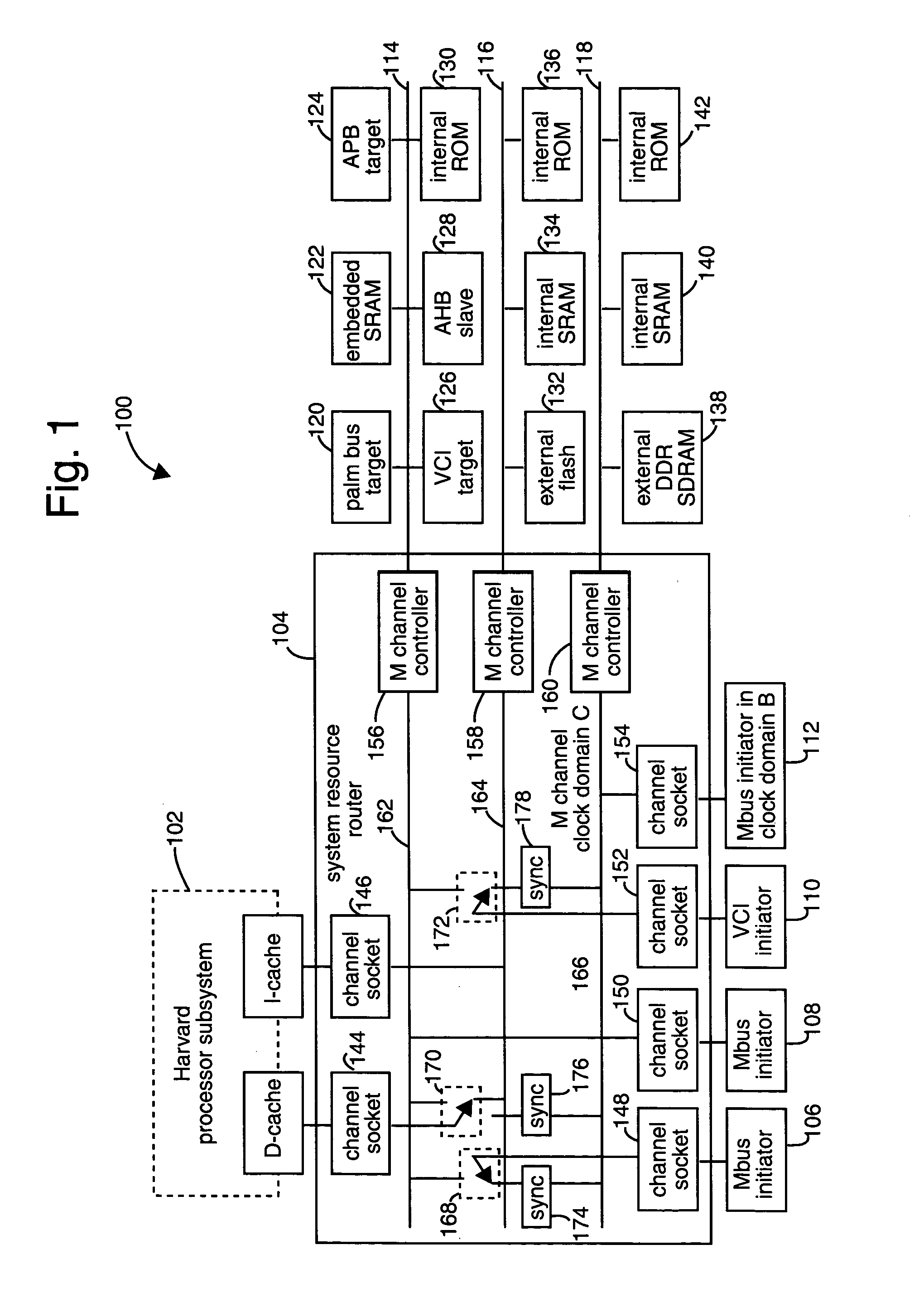
[0027]FIG. 1 shows a computer system embodiment of the present invention, and is referred to herein by the general reference numeral 100. The system 100 comprises a Harvard-architecture processor subsystem 102 connected through a system resource router 104 to a variety of resources on several buses. The system resource router 104 interfaces to a mix of bus initiators 106,108, 110, and 112 through channel sockets. It further interfaces to M-channel buses, e.g., a set of three M-channel buses 114, 116, and 118.

[0028] The M-channel bus 114 is shown with a typical com...


PUM


Abstract

A system resource router for SOC applications is described. Data-transfer initiators coupled to the router via one of a plurality of channel socket connections (144, 146, 148, 150, 152, 154) alternatively couple to internal M-channel buses (162, 164, 166) using transfer switches (168, 170, 172). Each internal M-channel bus connects to an external M-channel bus (114, 116, 118) populated by one or more transaction targets using an M-channel controller (156, 158, 160). The channel sockets, at least some of the data-transfer initiators, the internal M-channel buses, the external M-channel buses, and at least some of the transaction targets are all contained upon a single integrated circuit (IC) SOC device. Split reads and full duplex transactions are supported. Transactions can occur at different clock frequencies and bandwidths.

Description

CROSS REFERENCE TO RELATED APPLICATIONS [0001] This application is a continuation of U.S. Pat. No. 6,769,046, filed 5 Dec. 2000 (5 Dec. 2000), which is also a continuation in part of U.S. Pat. No. 6,601,126, filed 2 May 2000 (2 May 2000). Additionally, the prior U.S. Pat. No. 6,769,046 claims the benefits of the earlier filed U.S. Provisional Application No. 60 / 182,406 and U.S. Provisional Application No. 60 / 217,597. All of these documents are incorporated by reference for all purposes into this specification.BACKGROUND OF THE INVENTION [0002] 1. Field of the Invention [0003] The present invention relates generally to electronic circuits, and more specifically to functional modules on a single semiconductor integrated circuit. [0004] 2. Description of the Related Art [0005] The semiconductor art has advanced to the point where whole systems are preferably integrated onto a single-chip device. Processing speeds and architectures are such that very wide buses operated at near gigahert...

Claims


Application Information

Patent Timeline
IPC IPC(8): G06F13/40
CPCG06F15/7832G06F13/4022
Inventor ADAMS, LYLE E.MILLS, BILLY D.
Owner PALMCHIP CORP
Why Eureka
Try Eureka