Generator monitoring, control and efficiency

a technology of power generators and efficiency, applied in the direction of testing/monitoring control systems, instruments, specific gravity measurements, etc., can solve the problems of increasing, energy supply, such as electricity, not being able to keep up with the increase in demand, and being engulfed by an energy crisis, so as to achieve less time and less expensive

Inactive Publication Date: 2005-04-07
ROSEMOUNT ANALYTICAL
View PDF31 Cites 17 Cited by
  • Summary
  • Abstract
  • Description
  • Claims
  • Application Information

AI Technical Summary

Benefits of technology

[0015] An improved continuous emissions monitoring system is disclosed that has been adapted for use with the fossil fuel burning generators. The improved sample handling system for the continuous emissions monitoring emission monitoring system is much

Problems solved by technology

Worldwide, the demand for energy continues to increase while the supply of energy, such as electricity, is not always able to keep up with the increased demand.
For instance, recently the west coast of the United States has been gripped by an energy crisis as the demand for energy, and more specifically electricity, has increased faster than improvements in infrastructure and capacity.
Even running at capacity, there have been rolling brown-outs where entire grids are provided with reduced power for a period of time.
However, the construction of such a large-scale electrical generating facility takes years to complete and is a very costly process.
Many of these generators cannot be run full-time because they are powered by fossil fuel engines such as reciprocating diesel engines, reciprocating gas engines and gas turbines which generally produce relatively large emissions, especially if operated at less than optimal conditions.
The result of this is that while many parts of the western United States wrestle with dire electrical capacity and demand., thousands of back-up and peak generators in that very region sit idle.
Thus, in such situations, these generators also sit idle.
However such generators are typically oversized and their demanded internal use is periodic (higher when temperature is either higher or lower due to heating or air conditioned needs, higher when more people are in the building, and generally not used when the facility is closed).
Large-scale deployment of such generator is significanty limited by the lack of a cost-effective Continuous Emission Monitoring System (CEMS) solution and the economics of having to buy a

Method used


Image

  • Generator monitoring, control and efficiency
  • Generator monitoring, control and efficiency
  • Generator monitoring, control and efficiency

Examples


Embodiment Construction

[0025] The following description of the preferred embodiments is organized by function. However, the organization of the description should not be considered a limitation upon the invention, since various functions can be combined or omitted as desired.

[0026] Continuous Emission Monitoring System (CEMS)

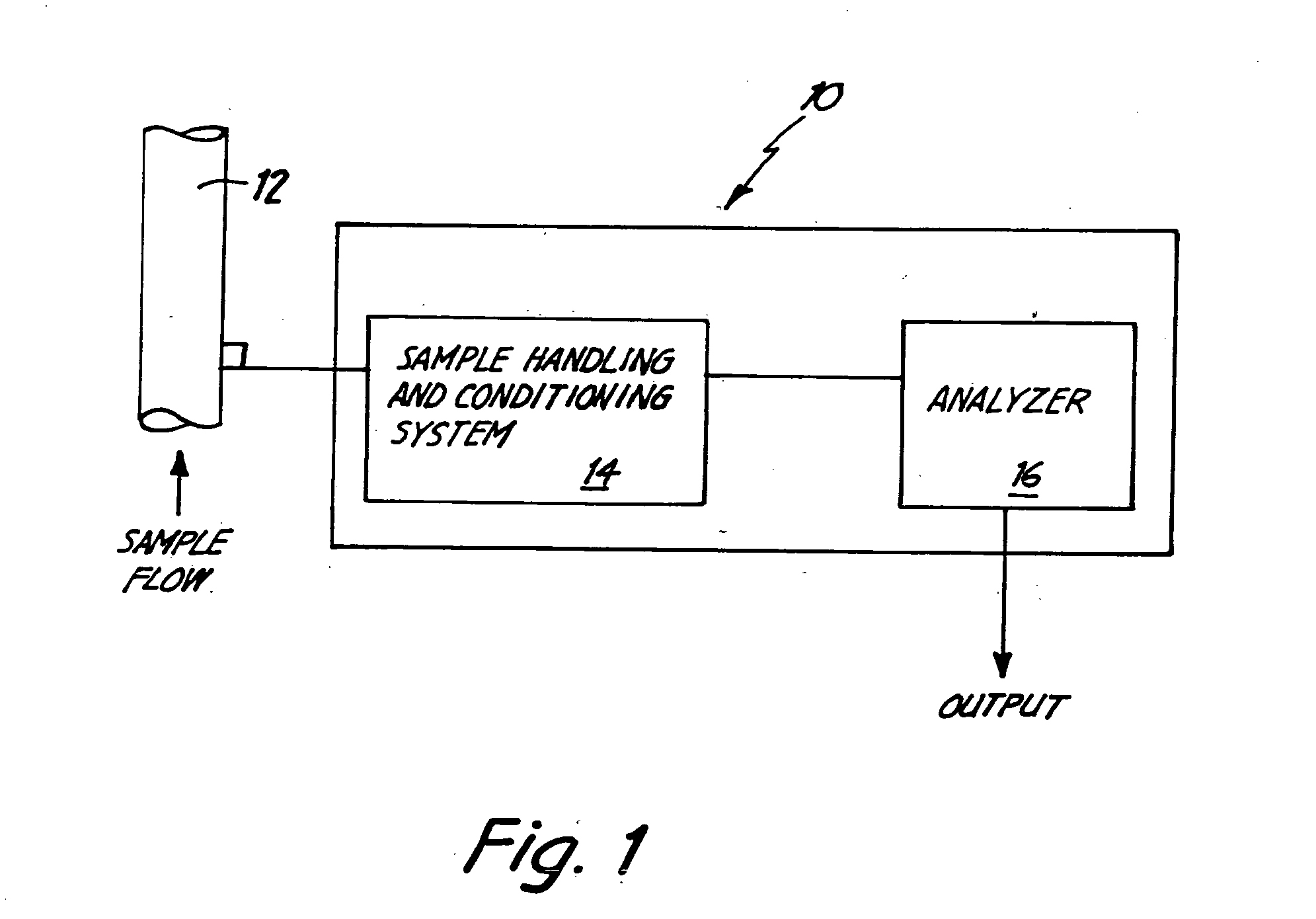
[0027]FIG. 1 illustrates a Continuous Emission Monitoring System 10 coupled to a process container such as pipe 12. System 10 periodically, or continuously, extracts samples of exhaust gas from container 12 and analyzes such gases for constituent components. Based upon the analysis of such components, information can be obtained about the combustion process itself. Once this information is known, various parameters can be adjusted or modified in order to optimize the combustion process. Generally, a Continuous Emission Monitoring System, such as system 10, includes two main components; a sample handling system and a suitable analyzer.

[0028] Sample handling system 14 is coupled to a...


PUM


Abstract

A system for generating electricity includes a generator and an interface. The generator is coupled to the interface and provides data to the interface regarding electricity generation. The interface is coupled to a control node for monitoring and controlling the generator. The control node may be coupled to the generator through a medium such as the internet. In some aspects of the invention, a continuous emissions monitoring system is provided for fossil-fuel based generators to enhance operation and reduce emissions of such generators.

Description

CROSS REFERENCE TO RELATED APPLICATIONS [0001] This application claims the benefit of earlier-filed co-pending provisional applications: 60 / 269,921 entitled CONTINUOUS EMISSIONS MONITORING SYSTEM FOR DIESEL GENERATORS, filed Feb. 19, 2001; 60 / 270,429 entitled WEB-BASED MICRO POWERPLANT MONITOR AND CONTROL, filed Feb. 21, 2001; 60 / 272,924 entitled WEB-BASED MICRO POWERPLANT MONITOR AND CONTROL, filed Mar. 2, 2001; 60 / 276,158 entitled CENTRALIZED DISPATCH SYSTEM FOR BACK-UP POWER SYSTEM, filed Mar. 15, 2001; and 60 / 229,291 entitled POWER GENERATING MONITORING, CONTROL AND EFFICIENCY, filed Jun. 19, 2001. All of the above: applications are fully incorporated herein by reference.BACKGROUND OF THE INVENTION [0002] The present invention relates to monitoring and control of small-scale power generators. [0003] Worldwide, the demand for energy continues to increase while the supply of energy, such as electricity, is not always able to keep up with the increased demand. For instance, recentl...

Claims


Application Information

Patent Timeline
IPC IPC(8): G05B23/02H04L29/08
CPCG05B23/0208G05B23/0294H04L67/306Y02T10/16Y02T10/166G05B2219/13G05B2223/06Y02T10/12
Inventor STAPHANOS, STEPHEN T.KEYES, MARION A.CACCIATORE, GARY G.
Owner ROSEMOUNT ANALYTICAL
Why Eureka
Try Eureka