
Integrated photovoltaic roofing system

Inactive Publication Date: 2005-04-07
SOLAR INTEGRATED TECH
View PDF55 Cites 80 Cited by
  • Summary
  • Abstract
  • Description
  • Claims
  • Application Information

AI Technical Summary

Benefits of technology

[0009] In some embodiments of an integrated photovoltaic roofing component and panel constructed in accordance with the invention, electrical interconnections between individual solar cells of a solar module are completed before the plurality of solar modules are adhered to the flexible membrane. As a result, the installer is not required to connect positive and negative electrodes of each individual solar cell, thereby reducing the electrical interconnections between all the solar cells and modules. Thus, the integrated photovoltaic roofing panel can be unrolled onto a roof of a building structure and installed and properly connected with fewer electrical components and connections than conventional combination photovoltaic systems.
[0013] Some embodiments of an integrated photovoltaic roofing system constructed in accordance with the invention include solar modules that are connected together via electrical connections made in a conduit that runs adjacent to the solar modules. In these embodiments, wires are attached to the electrodes of each of the photovoltaic modules. When the panel is assembled on a roof, the wires from the photovoltaic modules may be made connected together within the conduit. Thus, the conduit may provide strain relief for the connections and may protect the connections protected from the environment.
[0014] In some embodiments, a “quick-connect” is attached to each of the wires from the photovoltaic modules and to the wiring in the conduit. The use of “quick-connects” enables an installer to make the connections relatively quickly and easily.

Problems solved by technology

While such roofing materials may be satisfactory for the basic purpose of protecting a building structure from environmental elements, their use is essentially limited to these protective functions.
However, such systems typically require separate support structures that are bolted together to form an array of larger solar panels.
Further, the “add-on” solar panels are heavy and are more costly to manufacture, install and maintain.
Additionally, multiple penetrations of the roof membrane can compromise the water-tight homogeneity of the roof system, thereby requiring additional maintenance and cost.
These “add-on” solar panel systems may also be considered unsightly or an eyesore since they are attached to and extend from a roof.
These shortcomings provide a barrier to more building structures being outfitted with solar energy systems which, in turn, increase the dependence upon traditional and more limited and polluting energy resources.
Such wiring is typically performed by an electrician rather than a roofer, thereby increasing labor costs and complicating the installation.
Additional wire and connection components can also result in composite roofing panels requiring excessive field handling and weight, thereby making storage, transportation, and installation of panels more difficult and expensive.
Finally, increasing the number of wires and interconnections in a panel to be installed under field conditions increases the likelihood that the electrical connection in the panel will be broken, e.g., by variables associated with constructive field conditions or wire connections being exposed to inclement weather and / or other hazards (rodents, pigeons, etc.)

Method used


Image

  • Integrated photovoltaic roofing system
  • Integrated photovoltaic roofing system
  • Integrated photovoltaic roofing system

Examples


Embodiment Construction

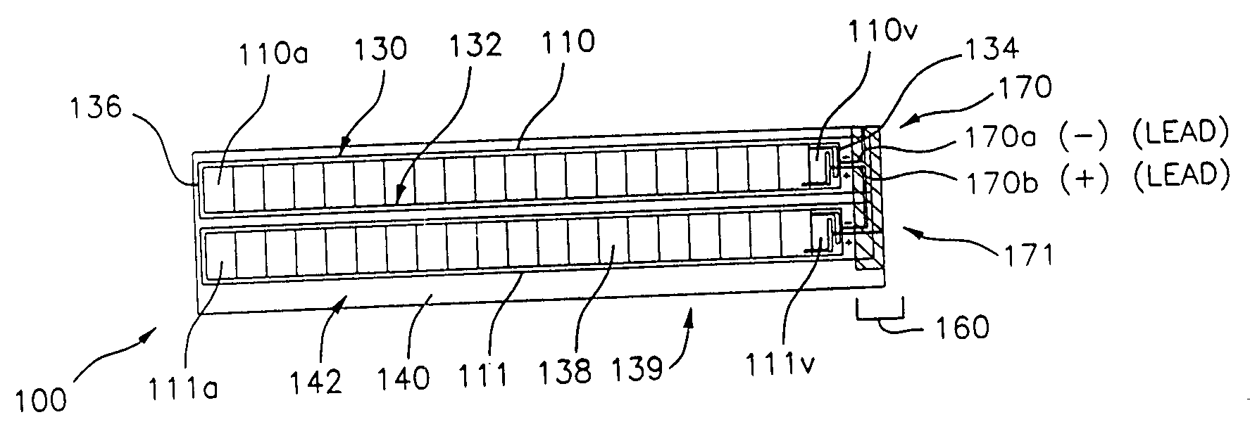
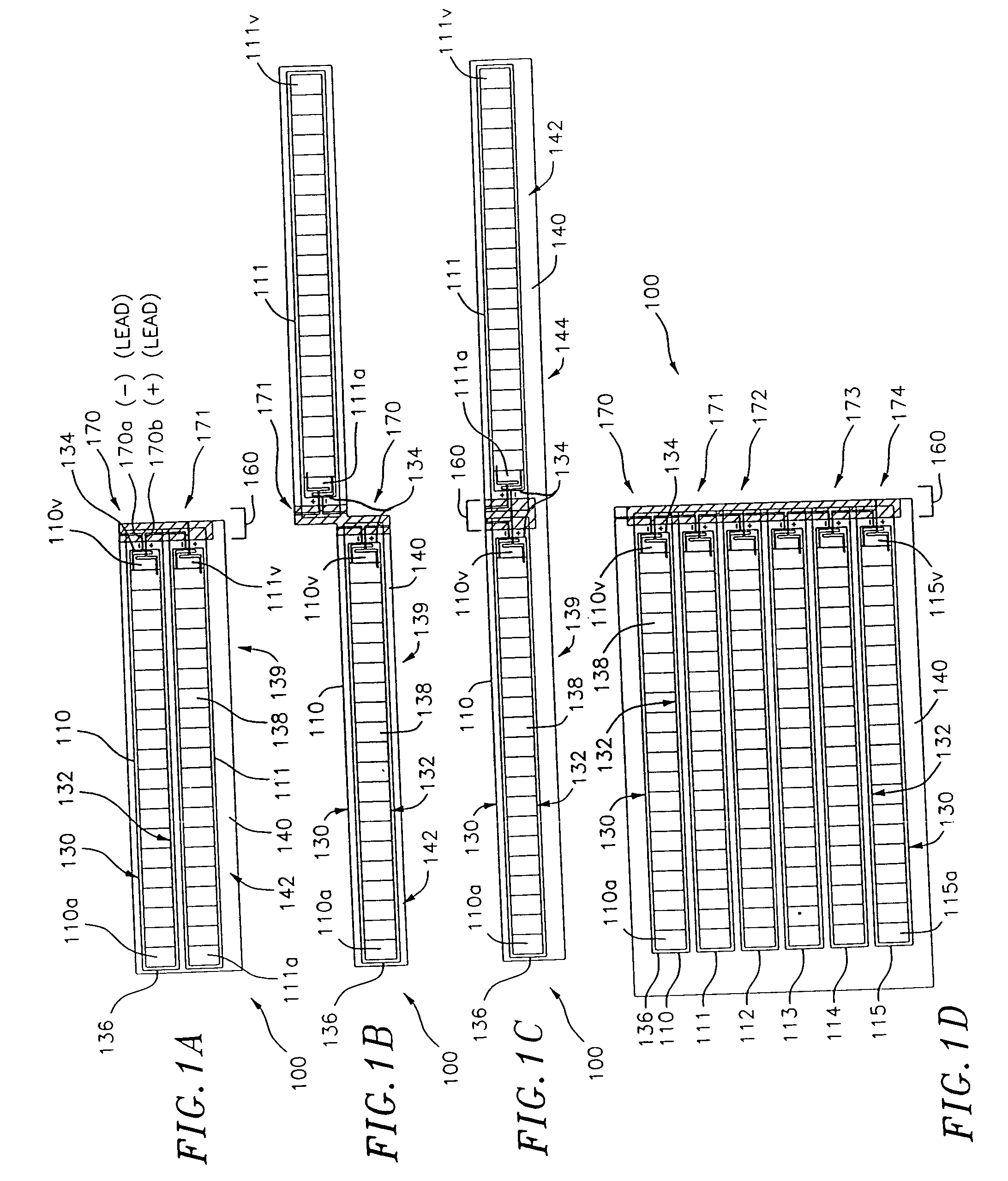
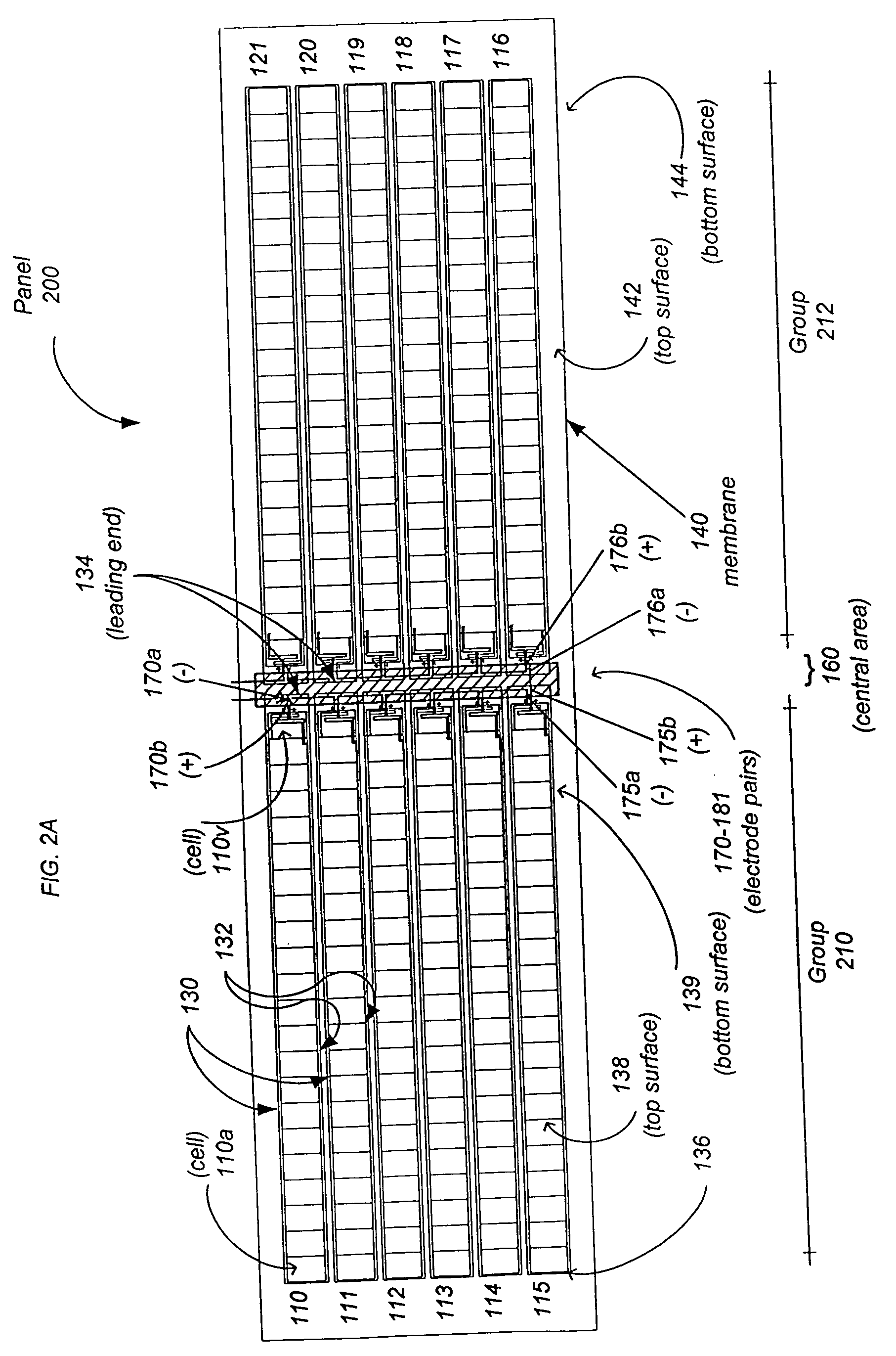
[0034] The present invention relates to an integrated roofing component, panel and system. The component, panel and system include a plurality of solar or photovoltaic modules (“PV modules”) attached to a flexible membrane sheet, such as a single-ply membrane. The modules are arranged adjacent each other, e.g., side-by-side or end-to-end. The ends of the modules have electrical connectors or electrodes that are arranged to face each other or are adjacent or aligned with each other.

[0035] In some embodiments, the electrical connectors extend from internal module electrodes of the solar modules and can extend through apertures formed in a bottom surface of the flexible membrane.

[0036] In some embodiments, photovoltaic modules are connected together by routing electrical connectors from each photovoltaic module into a conduit and connecting the electrical connectors in the conduit.

[0037] The electrical connectors conduct direct current (DC) electricity that may be connected directly...


PUM


Abstract

A combination roofing panel and solar module includes a flexible membrane sheet, such as a single-ply membrane sheet, and a plurality of elongated solar or photovoltaic modules arranged side-by-side, end-to-end, or adjacent each other. The modules are adhered to the flexible membrane, and the edges of the modules having electrical connectors or electrodes are arranged to face each other or be aligned with each other. The electrical connectors may be connected by a solder connection to module electrodes through apertures in a bottom surface of the flexible membrane and are connected in series. Alternatively, the electrical connectors may be connected to leads that terminate in a conduit located adjacent to the electrical connectors. In this case, connections between modules may be made by connecting the leads in the conduit. The series electrical connectors are connected directly to direct current (DC) electric devices, to a combiner box, to another panel or to an inverter which provides coverts direct current (DC) to alternating current electricity for use in residential, commercial or industrial building structures. The ends and elongated edges of a roofing component or panel having the flexible membrane and modules can be sealed for protection.

Description

FIELD OF THE INVENTION [0001] The present invention relates to roofing components, panels and systems, and more particularly, to a photovoltaic roofing component, panel and system having solar or photovoltaic modules integrated with a flexible membrane to protect a building from environmental elements while also generating electricity. DESCRIPTION OF RELATED ART [0002] Various types of roofing materials have been utilized to provide building structures protection from the sun, rain, snow and other weather and environment elements. Examples of known roofing materials include clay tiles, cedar and composition shingles and metal panels, and BUR materials, (e.g., both hot and cold applied bituminous based adhesives, emulsions and felts), which can be applied to roofing substrates such as wood, concrete and steel. Additionally, single-ply membrane materials, e.g., modified bitumen sheets, thermoplastics such as polyvinylchloride (PVC) or ethylene interpolymer, vulcanized elastomers, e.g....

Claims


Application Information

Patent Timeline
IPC IPC(8): E04D13/18H01GH01L25/00H01L31/048H01L31/05
CPCH01L31/02008Y02B10/12H02S20/23Y02E10/50Y02B10/14Y02B10/10Y02P80/20
Inventor STEVENSON, EDWARD J.KHOURI, BRUCE M.
Owner SOLAR INTEGRATED TECH
Learn More