Method for setting a desired operationg condition of a hybrid drive for a vehicle

a hybrid drive and operating state technology, which is applied in the direction of electric propulsion mounting, battery/cell propulsion, etc., can solve the problems of instantaneous power output of the vehicle electrical system deviating from their setpoint values, the torque adjustment of the second electric motor cannot be sufficiently accurate, and the vehicle electrical system voltage is rapidly and precisely controlled. , to achieve the effect of simple regulation of the charging and/or discharging capacity of the battery, fast and easy adjustment of the setpoint operating poin

Inactive Publication Date: 2005-04-07
ROBERT BOSCH GMBH
View PDF5 Cites 43 Cited by
  • Summary
  • Abstract
  • Description
  • Claims
  • Application Information

AI Technical Summary

Benefits of technology

[0006] In contrast, the method according to the present invention offers the advantage of enabling faster and easier adjustment of the setpoint operating point of the hybrid drive. Due to the fact that one of the electric motors may be controlled by voltage regulation and the other electric motor may be controlled by speed regulation, it becomes possible to integrate the regulation of the vehicle system voltage directly into the adjustment of the setpoint operating point of the hybrid drive. This may enable rapid and exact regulation of the vehicle system voltage. Since the vehicle system voltage may be directly coupled t...

Problems solved by technology

It is disadvantageous here that the torque of the second electric motor cannot be adjusted with sufficient accuracy.
Due to this inexact estimation, the adjustment of the torque of the second electric motor is faulty; as a result, the instantaneous output torque of the hybrid drive and the instantaneous power output of the vehicle electrical...

Method used


Image

  • Method for setting a desired operationg condition of a hybrid drive for a vehicle
  • Method for setting a desired operationg condition of a hybrid drive for a vehicle
  • Method for setting a desired operationg condition of a hybrid drive for a vehicle

Examples


Embodiment Construction

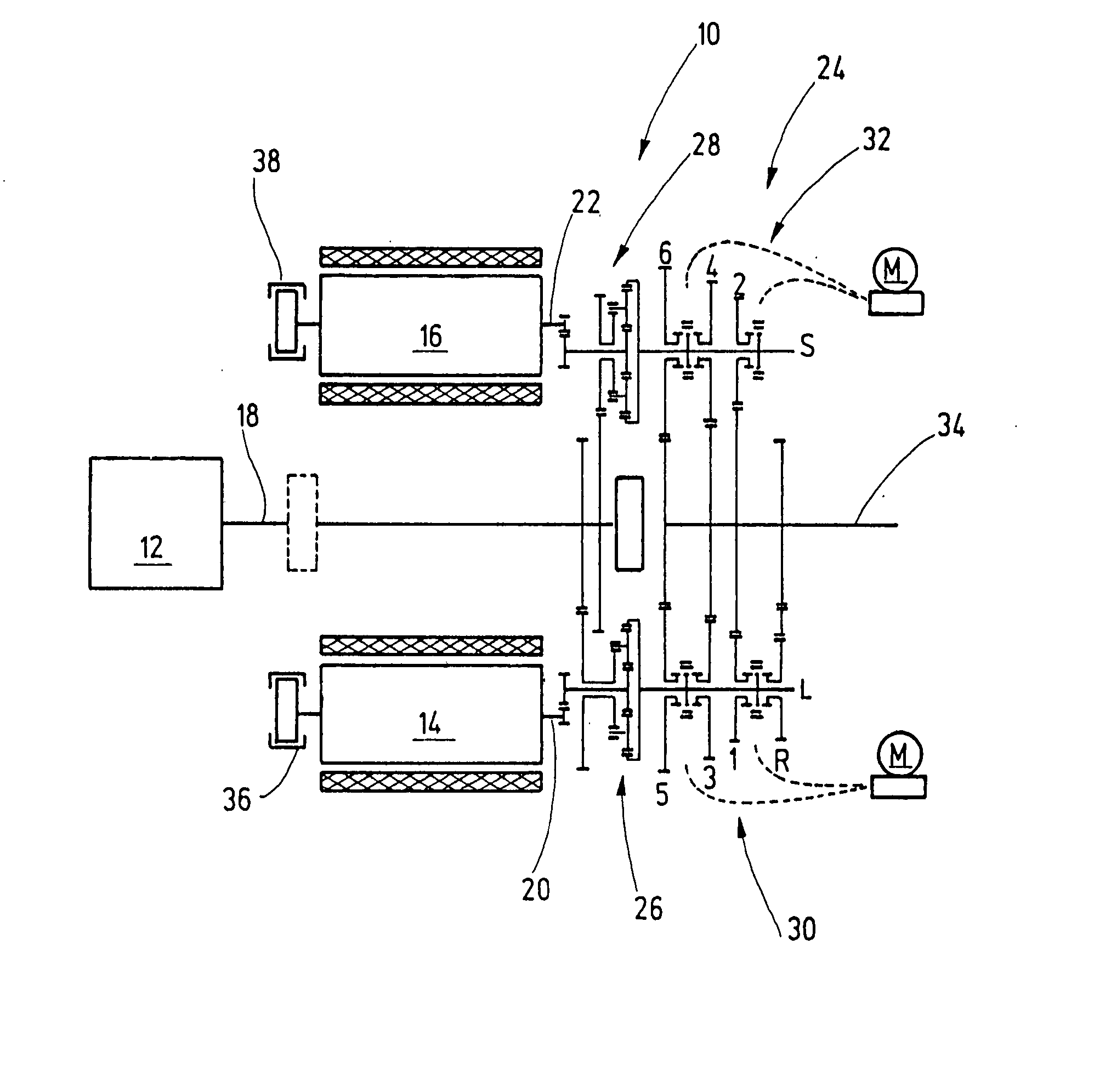
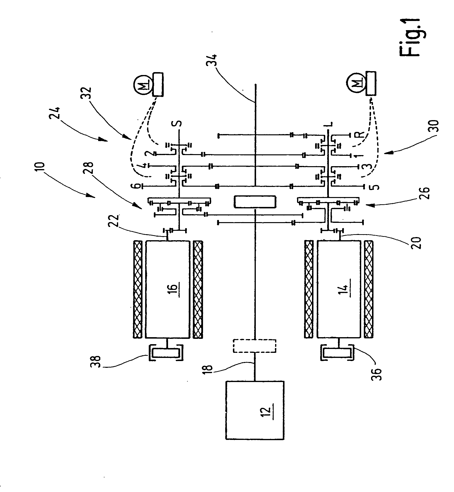
[0010]FIG. 1 is a schematic illustration of a hybrid drive of a motor vehicle labelled in its entirety with numeral 10. Hybrid drive 10 may include an internal combustion engine 12, a first electric motor 14 and a second electric motor 16. A crankshaft 18 of internal combustion engine 12 and drive shafts 20 and 22 of electric motors 14 and 16 may be operatively connected to a gearing system 24. Drive shaft 20 may be connected to a first planetary gearing 26, and drive shaft 22 may be connected to a second planetary gearing 28. A ring gear of planetary gearing 26 may be connected to a manual transmission 30, and a ring gear of planetary gearing 28 may be connected to a manual transmission 32. Manual transmissions 30 and 32 may be in turn operatively connected to an output shaft 34 of gearing system 24. Output shaft 34 may be operatively connected to a drive axle of the motor vehicle (not shown).

[0011] The design and mode of operation of a hybrid drive 10 of this nature are generally...


PUM


Abstract

A method for adjusting a setpoint operating state of a hybrid drive in a motor vehicle, the hybrid drive including an internal combustion engine and at least two electric motors as the drive motors, and the output shafts of the drive motors being operatively connectible to a drive train of the vehicle. A setpoint operating point of the hybrid drive is adjusted based on speeds and torques of the drive motors, the setpoint speeds and torques determined based on an instantaneous power demand on the hybrid drive and an instantaneous electrical power demand of an electrical system of the vehicle, and at least one of the electric motors is controlled by voltage regulation and the other electric motors controlled by speed regulation.

Description

FIELD OF THE INVENTION [0001] The present invention relates to a method for adjusting a setpoint operating state of a hybrid drive in a vehicle, the hybrid drive including an internal combustion engine and at least two electric motors as the drive motors, and the output shafts of the drive motors being capable of being operatively connected to a drive train of the vehicle. BACKGROUND INFORMATION [0002] Hybrid drives for vehicles are known. In the case of the hybrid drives discussed here, an internal combustion engine is combined with two electric motors, so that a plurality of drive sources is available to the vehicle. In accordance with demands specified by a vehicle driver, the drive sources can selectively supply their input torques to a drive train of the vehicle. In a manner that is known per se, this results in different possible drive configurations depending on actual driving situations, the drive configurations serving, e.g., to enhance driving comfort and reduce energy use...

Claims


Application Information

Patent Timeline
IPC IPC(8): B60K1/02B60K6/445B60K6/547B60L11/18B60L15/20B60L50/16B60W10/08B60W20/00F16H3/091F16H3/72
CPCB60K1/02Y02T10/7275B60K6/547B60L11/123B60L11/14B60L15/20B60L2240/421B60L2240/423B60W10/08B60W20/00B60W2510/244B60W2710/081B60W2710/083F16H3/0915F16H3/728F16H37/0813Y02T10/6217Y02T10/646Y02T10/7077Y02T10/648Y02T10/6239B60K6/445B60L50/61B60L50/16Y02T10/62Y02T10/64Y02T10/7072Y02T10/72Y02T10/70B60W20/10B60W10/06
Inventor EISENHARDT, MARTINHOETZER, DIETERTUMBACK, STEFAN
Owner ROBERT BOSCH GMBH
Why Eureka
Try Eureka