Acoustic diffusers for acoustic field uniformity

a technology of acoustic field and diffuser, which is applied in the direction of cleaning using liquids, instruments, transportation and packaging, etc., can solve the problems of reducing the field maxima and minima, and achieve the effect of reducing the range of intensities, reducing the cost, and increasing the uniformity

Inactive Publication Date: 2005-04-07
FSI INTERNATIONAL INC
View PDF43 Cites 8 Cited by
  • Summary
  • Abstract
  • Description
  • Claims
  • Application Information

AI Technical Summary

Benefits of technology

The present invention involves systems and methods in which a sound diffusing system is used to help diffuse the sound field established within a processing liquid during the course of a treatment in which one or more wafers are immersed in the sonified liquid. The sound diffusing system helps to minimize the range of intensities among sound waves generated in the processing fluid. Greater uniformity can save in the cost of chemical cleaners, can provide superior cleanliness, and can reduce the potential to damage features on the wafers by reducing the acoustic intensity at the field maxima.
In one aspect, then, the present invention relates to using a sound diffusing system including a plurality of sound diffusing elements that cooperatively function to help sonify the processing volume more uniformly, e.g., with a narrower distribution of sound wave intensities. The individual diffusing elements may be discrete from one another or may be integrally formed. If integrally formed on a substrate or otherwise, the sound diffusing system may include diffusing elements that may be formed in a material as protuberances and / or depressions. In many embodiments, the sound diffusing system is provided by one or more physical structures positioned in the acoustic pathway between the acoustic energy source and the wafer(s) being processed to help sonify the processing volume occupied by the wafer(s) more uniformly. Such physical structures desirably dampen field maxima and minima while still allowing sufficient acoustic energy to pass to achieve desired field strength.
In another aspect, the present invention relates to individual diffusing elements that constitute all or a portion of a sonic diffusing system. In general, the diffuser elements of the present invention allow sound energy to pass, but preferably diffuse the sound so that maxima and minima in field variation are dramatically dampened. The effect is very analogous to the way frosted glass diffuses light passing through it. A sonic diffusing element preferably comprises at least one surface feature that helps control refraction, diffraction, phase modulation, and / or phase shifting of sound energy. Such diffusing characteristics of such elements may depend upon physical structure, and / or other factors. For example, a sonic diffuser may include one or more of topographic features (e.g., surface texture), surface curvature features, protuberances, depressions, sonic velocity controlling features, diffraction elements such perforations or the like, combinations of these, or the like to help more uniformly sonify the process tank.
According to another aspect of the present invention, an apparatus for immersion processing wafers includes (1) an immersion processing tank in which one or more wafers are positioned in a processing liquid during a treatment, (2) at least one sound source that is acoustically coupled to the processing liquid and that produces a sound field in the processing liquid contained in the processing tank during a treatment, and (3) a sound diffusing system comprising a plurality of sound diffusing elements positioned in a manner effective to diffuse sound energy transferred from the source to the processing liquid.
According to another aspect of the present invention, an apparatus for immersion processing wafers includes (1) an immersion processing tank in which one or more wafers are positioned in a processing liquid during a treatment, (2) at least one sound source that produces a sound field in the processing liquid contained in the processing tank, and (3) a sound diffusing system comprising at least one directionally phase modulating element positioned in a manner effective to reduce interference of sound energy in the processing liquid.

Problems solved by technology

Such physical structures desirably dampen field maxima and minima while still allowing sufficient acoustic energy to pass to achieve desired field strength.

Method used


Image

  • Acoustic diffusers for acoustic field uniformity
  • Acoustic diffusers for acoustic field uniformity
  • Acoustic diffusers for acoustic field uniformity

Examples


Embodiment Construction

The embodiments of the present invention described below are not intended to be exhaustive or to limit the invention to the precise forms disclosed in the following detailed description. Rather the embodiments are chosen and described so that others skilled in the art may appreciate and understand the principles and practices of the present invention.

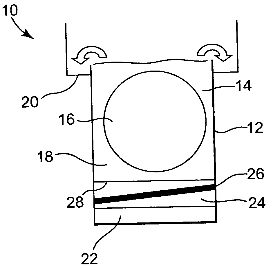
The principles of the present invention may be practiced in any kind of equipment (e.g., single wafer tools or batch processing tools) in which one or more wafers are immersed in a sonified bath during the course of a treatment. One suitable and representative processing tank 10 with acoustic, e.g., megasonic, capabilities of the type used in a wet bench tool (such as the MAGELLAN® system commercially available from FSI International, Inc., Chaska, Minn.) is shown schematically in cross-section in FIG. 1. Tank 10 may be used to treat wafer(s) either singly or in batches. Tank 10 generally includes a housing 12 defining a process cham...


PUM


Abstract

Apparatuses and methods for processing semiconductor wafers. In one embodiment, an apparatus includes an immersion processing tank in which one or more wafers are positioned in a processing liquid during a treatment, at least one sound source that is acoustically coupled to the processing liquid and that produces a sound field in the processing liquid contained in the processing tank during a treatment, and a sound diffusing system comprising a plurality of sound diffusing elements positioned in a manner effective to diffuse sound energy transferred from the source to the processing liquid. In another embodiment, the sound diffusing system includes at least one directionally phase modulating element positioned in a manner effective to reduce interference of sound energy in the processing liquid. Related methods are also described.

Description

FIELD OF THE INVENTION The field of this invention relates to microelectronic processing systems and methods for treating wafers immersed in a process liquid in the presence of acoustic energy, and more particularly, this invention relates to such systems and methods in which a sound diffusing system is used to improve the uniformity of the sound field established in the process liquid. BACKGROUND OF THE INVENTION Acoustic energy, such as megasonic energy in the megahertz frequency range, is used in the microelectronics industry in the course of manufacturing microelectronic devices. In a representative system, a source of megasonic energy is coupled to a process chamber. Many semiconductor processing systems, for example, having megasonic capabilities are known. The source can be external to the process chamber or internal. Megasonic energy is often used in the course of cleaning and rinsing treatments. For instance, U.S. Pat. Nos. 4,869,278; 5,017,236; 5,365,960; and 6,367,493 d...

Claims


Application Information

Patent Timeline
Patent Type & Authority Applications(United States)
IPC IPC(8): B08B3/12G10K11/20H01L21/00H03G3/00
CPCB08B3/12H01L21/67057G10K11/20
Inventor CHRISTENSON, KURT K.
Owner FSI INTERNATIONAL INC
Why Eureka
Try Eureka