Dischargers for powders

a technology of discharging bins and powders, which is applied in the field of discharging bins, can solve the problems of affecting the flow of products, many undesirable consequences, and no advantage of steepening the walls of the hopper above the angle required, so as to improve the flowability of the hopper, and reduce the amount of headroom

Inactive Publication Date: 2005-04-07
A B DICK CO
View PDF9 Cites 0 Cited by
  • Summary
  • Abstract
  • Description
  • Claims
  • Application Information

AI Technical Summary

Benefits of technology

[0013] By reducing the angle of internal friction or the angle of sliding friction and providing a sloped wall in the range of angles specified, surprisingly it has been found that many of the problems referred to above are done away with and a relatively small outlet can be used. In this way the mass flow angle is less dependent on powder properties and a reliable flow regime can be produced from such an arrangement.
[0021] Suitably, there is provided means for lowering the angle of internal friction and for lowering the angle of sliding friction between the powder and the discharger surface, which comprises a vibrator for vibrating the discharger surface.
[0031] It has been found that in dischargers according to preferred embodiments of the present invention increasing the slope of a hopper in one region beyond 400 takes it beyond the critical angle required for mass flow, but improves the flowability of the hopper. Further, a steep portion of the hopper, combined with an optimised hopper layout, occupies less headroom than would be required for a conventional mass flow hopper design, especially when the angle of sliding friction is high. In preferred embodiments, this hopper layout improves the flowability of the hopper to the extent that the outlet size need only be a small fraction of Bc, the critical gravity flow arching dimension of a right circular conical hopper. The flow through small outlet sizes is a significant advantage when the powder has cohesive strength and also when the control of flow rate is important such as in dispensing pharmaceutical powders or measuring out food products and ingredients.
[0032] With preferred embodiments of the present invention, one hopper design will reliably handle powders with a very wide range of flow properties. The choice of hopper width and outlet size will be based more on the required flow rate and accuracy of control than on the critical arching dimensions.

Problems solved by technology

First, the product in the hopper must not form an arch, which interrupts the flow of the product.
If the hopper walls are not steep enough the product will form a very steep sided flow channel within otherwise stagnant material, which results in many undesirable consequences.
In general, there is no advantage to making the walls of a hopper steeper than the angle required for mass flow.
In spite of the advantages of plane flow, it is not often used in practice because the problem of collecting the product below the slot outlet can be relatively complex.
One of the reasons collecting material under a slot is complex is that the product must shear in a certain way and change its direction of flow.
Development of the correct shear planes and the forces required to change the direction of flow can be difficult to achieve.

Method used


Image

  • Dischargers for powders
  • Dischargers for powders
  • Dischargers for powders

Examples


first embodiment

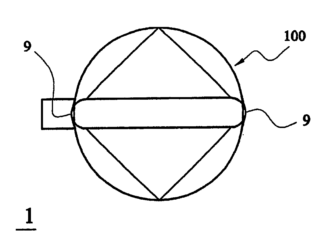
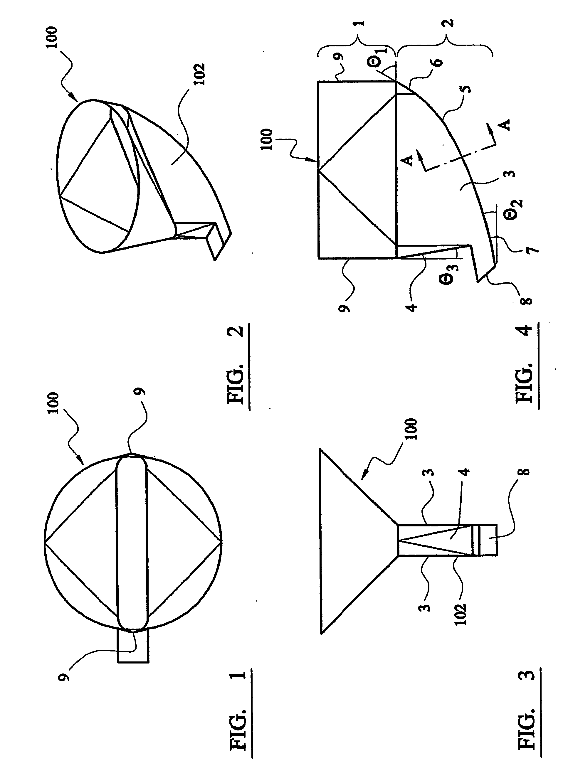
[0052] In FIGS. 1-4 of the drawings that follow, the present invention comprises a discharger 100 having a hopper 102 and an outlet 8. The hopper 102 comprises an upper section 1 and a lower section 2. Upper section 1 can be added to lower section 2 if required. The upper section 1 will ordinarily be required when the discharger 100 is used as part of a bin, but may not be required in the form shown if the lower section is used as part of a flexible walled storage container or other type of process equipment. Lower section 2 of hopper 102 is of a rectangular box shape with rounded ends and comprises side walls 3, an end wall 4 and a discharger surface 5 as a lower wall defining a graduated curved surface with, in the normal operating orientation shown, a steep section 6 and a shallow section 7 at the lower end thereof, the latter extending to a discharger outlet B. Upper section 1 of hopper 102 includes end walls 9 that diverge downwardly.

[0053] The sections 6 and 7 together compris...

second embodiment

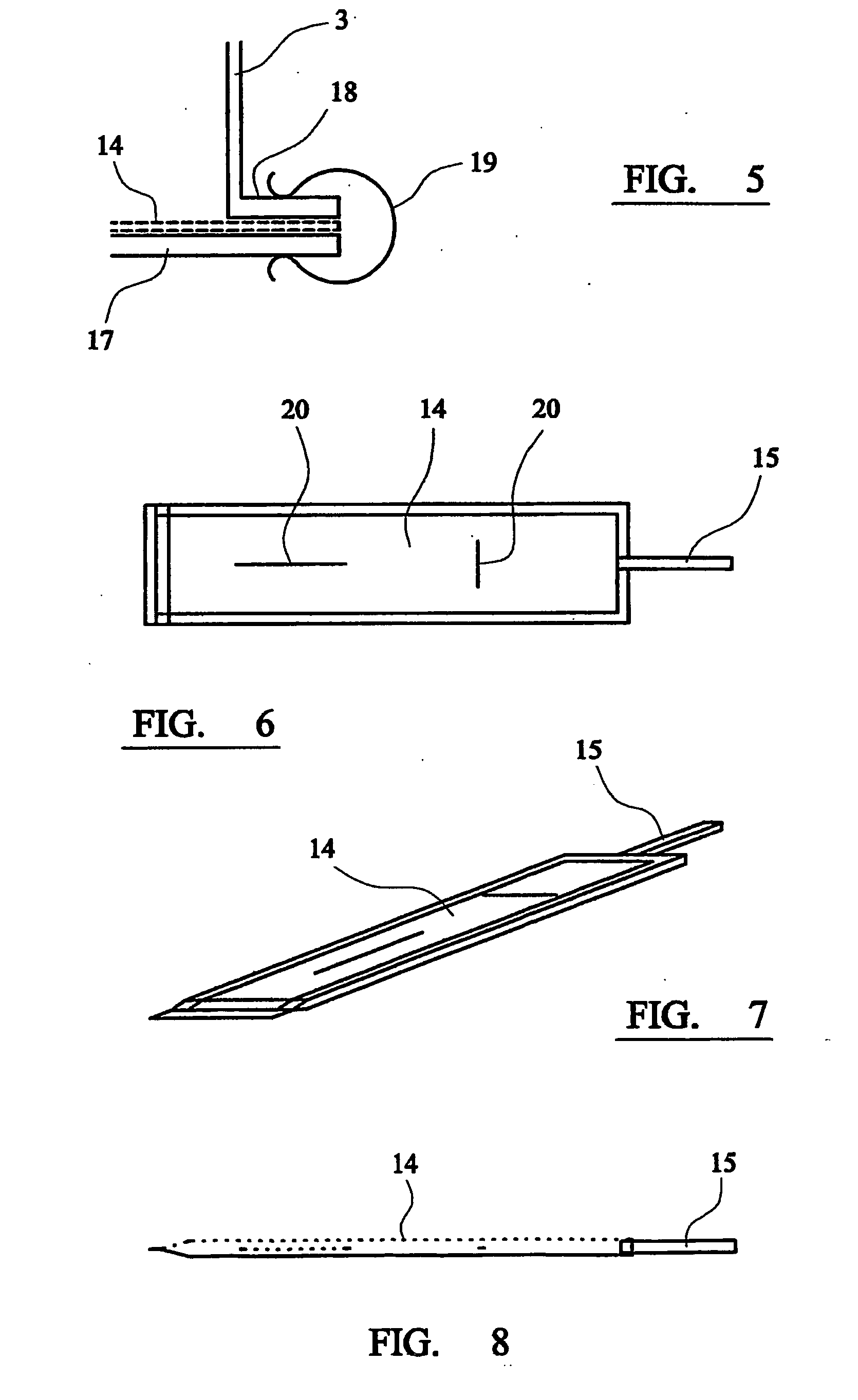
[0062] In FIGS. 9-13, the lower wall 12 is shown as curved, with a flattened U-shape, in its cross-section (see FIG. 11) i.e. across the discharger surface. Experience has shown that this tends to direct the flow toward the centreline of the sliding surface and minimises the tendency of the powder to squeeze between the sidewall and the vibrating surface during operation.

[0063] As shown in FIG. 13, an additional flexible strip 10 is shown mounted to the sidewall to seal the necessary gap 13 between the sidewalls 3 and the vibrating surface 12. The side walls 3 are shown as parallel to one another in plan in FIGS. 9-12 but they may diverge from the back to the outlet to further relieve the confining pressures on the powder as it flows down the discharger surface 5.

[0064] This second embodiment will be used when handling powders that cannot be conditioned by blowing air into the mass if, for example the permeability of the powder is too high. Both the removal of the angle of repose o...


PUM


Abstract

There is disclosed a discharger (100) for a powder, the discharger comprising a hopper (102) and an outlet (8), the hopper comprising a discharging surface (5) over which, in use, a powder flows, and means (14, 15) for lowering the angle of internal friction of the powder or for lowering the angle of sliding friction between the powder and the discharger surface, wherein the discharging surface comprises surfaces at least two angles that are progressively shallower towards the outlet and in which a steeper part of the discharging surface in use is steeper than 40° from the horizontal. A method of use of such a discharger is also disclosed.

Description

FIELD OF THE INVENTION [0001] The present invention relates to dischargers for powders. [0002] In particular, but without limitation, the present invention is relevant to the field of storage bins for powders, such as wheat flour. BACKGROUND TO THE INVENTION [0003] Dischargers for powders generally comprise a hopper and an outlet. [0004] Several aspects must be considered in the design of hoppers. First, the product in the hopper must not form an arch, which interrupts the flow of the product. If and when the arch collapses the product will often surge from the hopper. It is well known that arching can be eliminated if the opening at the outlet of the hopper is large enough. For a right circular conical hopper, the critical gravity flow-arching dimension for a particular material is designated as Bc. As will be seen below, the present invention permits the use of a discharge opening that is only a fraction of Bc. [0005] A second consideration in the design of hoppers is that the hop...

Claims


Application Information

Patent Timeline
Patent Type & Authority Applications(United States)
IPC IPC(8): B65D88/28B65D88/66B65D88/72
CPCB65D88/28B65D88/72B65D88/66
Inventor DICK
Owner A B DICK CO
Why Eureka
Try Eureka