Capacitance detector circuit, capacitance detection method, and fingerprint sensor using the same

a capacitance detection and capacitance detection technology, applied in the direction of acquiring/reconfiguring fingerprints/palmprints, resistance/reactance/impedence, instruments, etc., can solve the problem that the capacitance detector circuit is unable to precisely detect a capacitance change, the capacitance detector circuit is unable to completely remove disturbing noise components, and the effect of disturbance noise added to the column lines is relatively reduced and the gain of detection is heightened

Active Publication Date: 2005-04-07
SYNAPTICS INC
View PDF8 Cites 101 Cited by
  • Summary
  • Abstract
  • Description
  • Claims
  • Application Information

AI Technical Summary

Benefits of technology

As described above, the capacitance detector circuit of the preferred embodiments of the present invention multiplexes the capacitances in accordance with the code having orthogonality to drive a plurality of column lines at a time, and sums changes in capacitance at a plurality of intersections to detect the capacitance. The effect of disturbance noise added to the column lines

Problems solved by technology

Known capacitance detector circuits are still subject to the effect of noise occurring in the capacitive sensor even if the offset component taking place in circuits containing an amplifier is removed.
In other words, the capacitance detector circuit is unable to precisely detect a capacitance change because of di

Method used


Image

  • Capacitance detector circuit, capacitance detection method, and fingerprint sensor using the same
  • Capacitance detector circuit, capacitance detection method, and fingerprint sensor using the same
  • Capacitance detector circuit, capacitance detection method, and fingerprint sensor using the same

Examples


first preferred embodiment

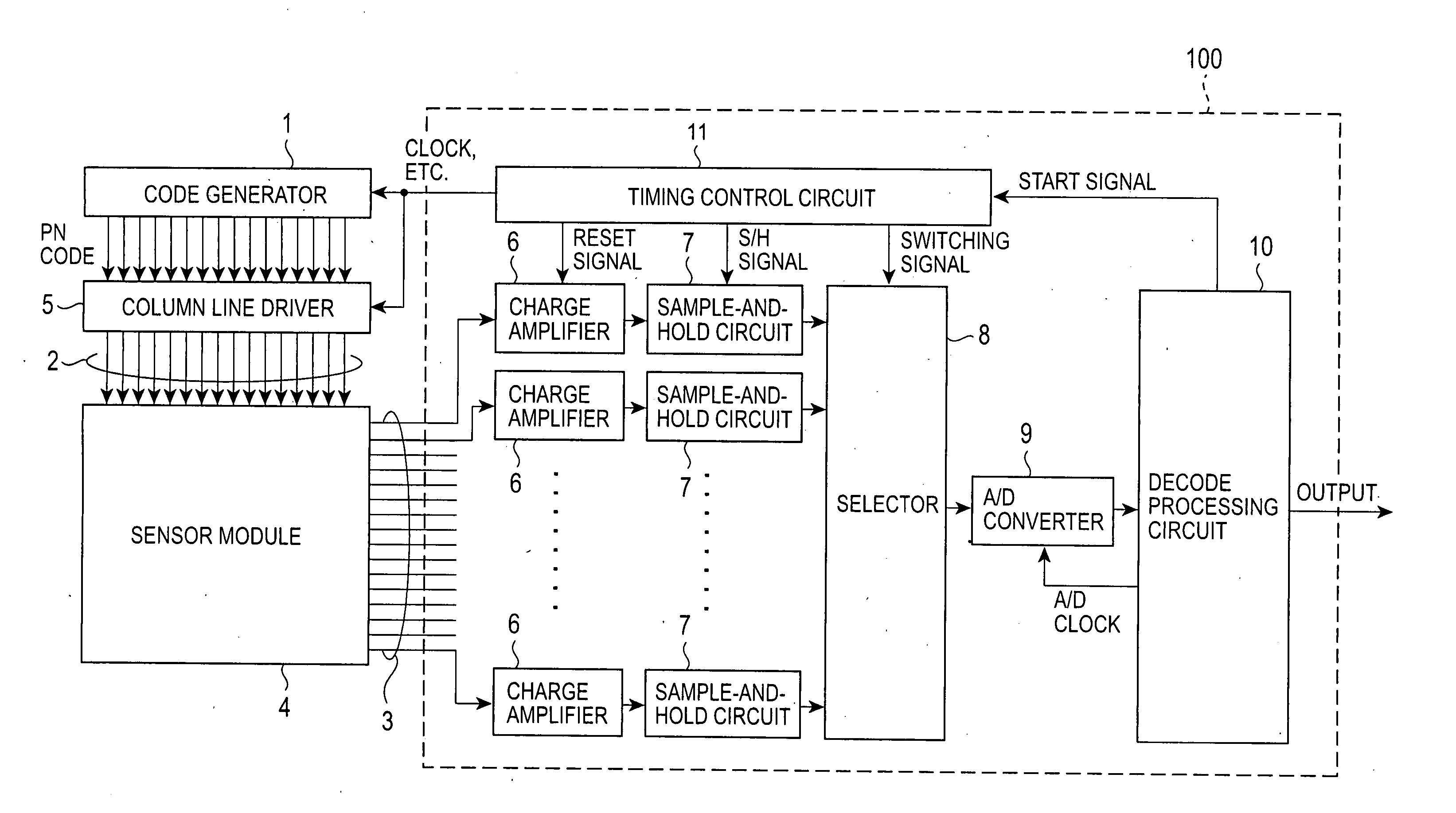
A capacitance detector circuit of preferred embodiments of the present invention is for use in a matrix capacitive sensor having a plurality of column lines and a row line intersecting the column lines and detects a change in capacitance at an intersection of a column line and a row line. The capacitance detector circuit includes a code generating unit for generating a code having orthogonality in time sequence to output the generated code as a column drive signal, a column line drive unit for concurrently driving a predetermined column lines which are selected in response to the code, a capacitance detecting unit, connected to the row line, for detecting a voltage by converting a total sum of changes in capacitance at intersections of the selected column lines into the voltage to output the detected voltage, and a decode processing unit for performing a predetermined calculation on a data string of the detected voltage output in time sequence on a per row line basis every cycle of...

second preferred embodiment

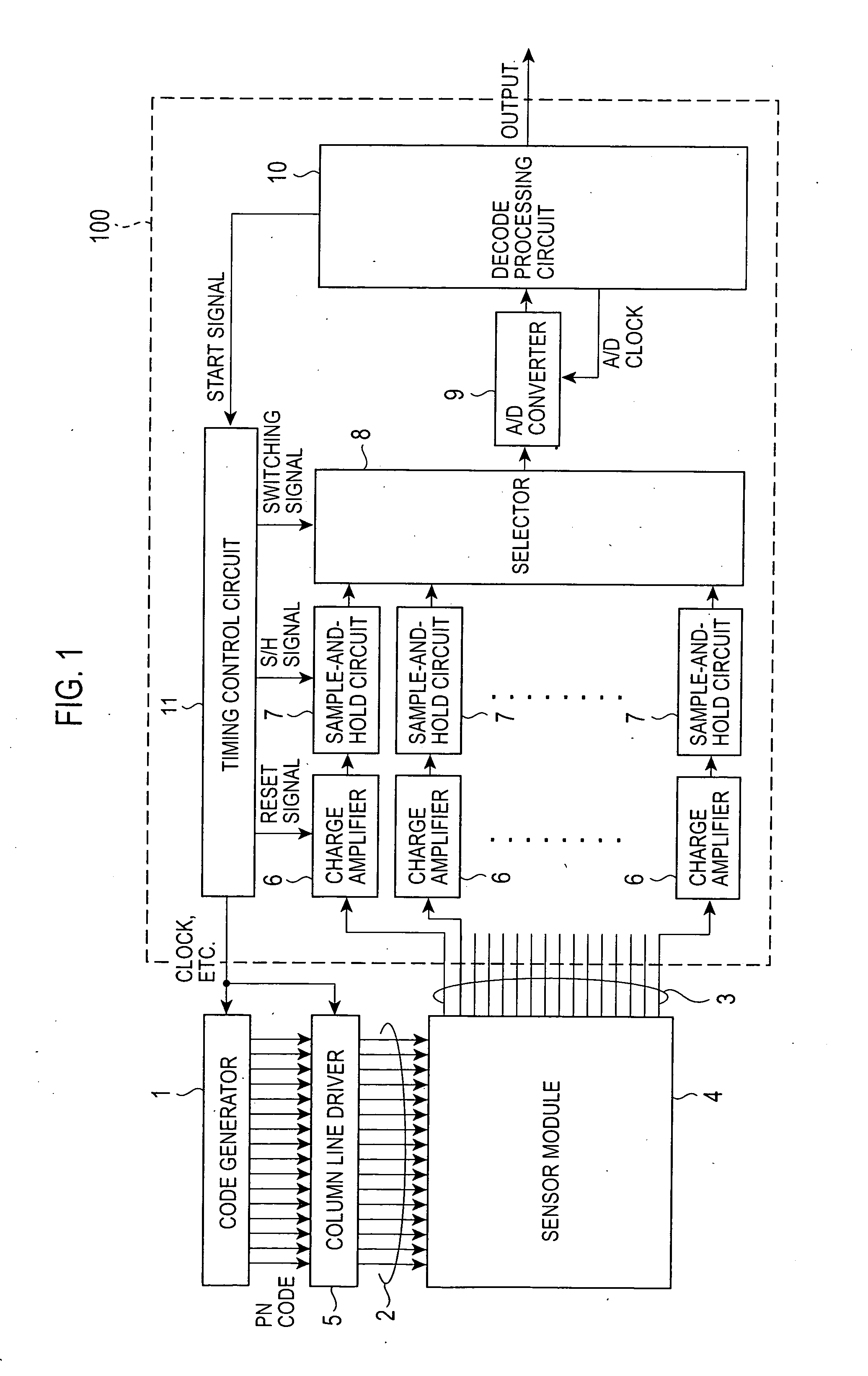
A second preferred embodiment of the present invention is described below with reference to FIG. 1. The discussion of the elements and operation identical to those of the first preferred embodiment is omitted here. In the capacitance detector circuit of the second preferred embodiment, the PN code generator 1 circulates the generated PN code for a plurality of cycles, and the column line driver 5 outputs the drive pulse train for the plurality of cycles to the column line array 2 to acquire measurement data for the plurality of cycles. In response to the PN code, the decode processing circuit 10 performs the multiplication and summing process on the acquired measurement data, thereby obtaining voltage data corresponding to the capacitance of each sensor element.

Referring to FIG. 14A, a spread gain is obtained. More specifically, in spread spectrum communication, spread gain GP is determined if transmission bandwidth BT is large with respect to bandwidth Bi of information as in th...

third preferred embodiment

Referring to FIG. 17, a capacitance detector circuit of a third preferred embodiment of the present invention is described below. FIG. 17 is a block diagram illustrating the structure of a code generator 1B and a column line driver 5 in accordance with the third preferred embodiment of the present invention. Elements in the third preferred embodiment identical to those discussed with reference to the second preferred embodiment are designated with the same reference numerals.

As in the second preferred embodiment, a measurement operation of shifting the bit train of the PN code and multiplexing the capacitance of the sensor elements on a per row line basis is performed for a plurality of cycles. The difference of the third preferred embodiment from the second preferred embodiment is that the multiplexing operation is performed using a different PN code for each cycle. More specifically, two types of PN codes are generated, and each time one cycle is completed, the detector switche...


PUM


Abstract

A capacitance detecting circuit of a capacitive sensor having a plurality of column lines and a row line intersecting the column lines detects a change in capacitance at an intersection of a column line and a row line. The circuit includes a PN code generating unit for generating a code having orthogonality in time sequence to output the generated code as a column drive signal, a column line drive unit for driving a predetermined one of the column lines which are selected in response to the code, a capacitance detecting unit, connected to the row line, for detecting a voltage by converting a total sum of changes in capacitance at intersections of the selected column lines into the voltage to output the detected voltage, and a decode processing unit for performing a predetermined calculation on the detected voltage output from the capacitance detecting unit and the code to determine a voltage value responsive to the capacitance change at the intersection.

Description

BACKGROUND OF THE INVENTION 1. Field of the Invention The present invention relates to a circuit and a method for detecting a low capacitance and a fingerprint sensor using the circuit. 2. Description of the Related Art Pressure sensitive capacitive sensors have been developed as a fingerprint sensor that is considered as the most promising technique in biometrics. The pressure sensitive capacitive sensor includes one film bearing column lines spaced at predetermined intervals on the surface thereof and the other film bearing row lines spaced at predetermined intervals on the surface thereof. The two films are arranged to face each other with an insulator interposed therebetween to allow a predetermined separation therebetween. The films of the pressure sensitive capacitive sensor are deformed in response to the roughness of the fingerprint when a finger is placed onto the sensor. The separation between the column line and the row line changes depending on location, and the shap...

Claims


Application Information

Patent Timeline
IPC IPC(8): G01R27/26G06K9/00G11C27/02
CPCG01R27/2605G11C27/026G11C27/024G06K9/0002G06V40/1306
Inventor UMEDA, YUICHISATO, JUNICHI
Owner SYNAPTICS INC
Why Eureka
Try Eureka