Image processing apparatus and method, and calibration device for position and orientation sensor

Active Publication Date: 2005-04-07
CANON KK
View PDF5 Cites 36 Cited by
  • Summary
  • Abstract
  • Description
  • Claims
  • Application Information

AI Technical Summary

Benefits of technology

Using the image processing apparatus and method according to the present invention, the user can easily change the contents of a virtual CG without interrupting the current operation.
According to the present invention, since the position and orient

Problems solved by technology

However, along with an elapse of time, an environment changes and position and orientation information may go wrong.
Some positi

Method used


Image

  • Image processing apparatus and method, and calibration device for position and orientation sensor
  • Image processing apparatus and method, and calibration device for position and orientation sensor
  • Image processing apparatus and method, and calibration device for position and orientation sensor

Examples


Example

First Embodiment

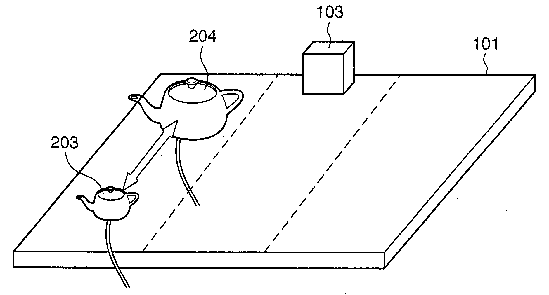
In this embodiment, in a system wherein a three-dimensional computer graphics (3D CG) of a teapot as a virtual object is superimposed on a real object which can be picked up and manipulated by the user so as to allow the user to observe a virtual teapot via a head-mounted display (HMD), the user can change the 3D CG of the teapot by a simple operation.

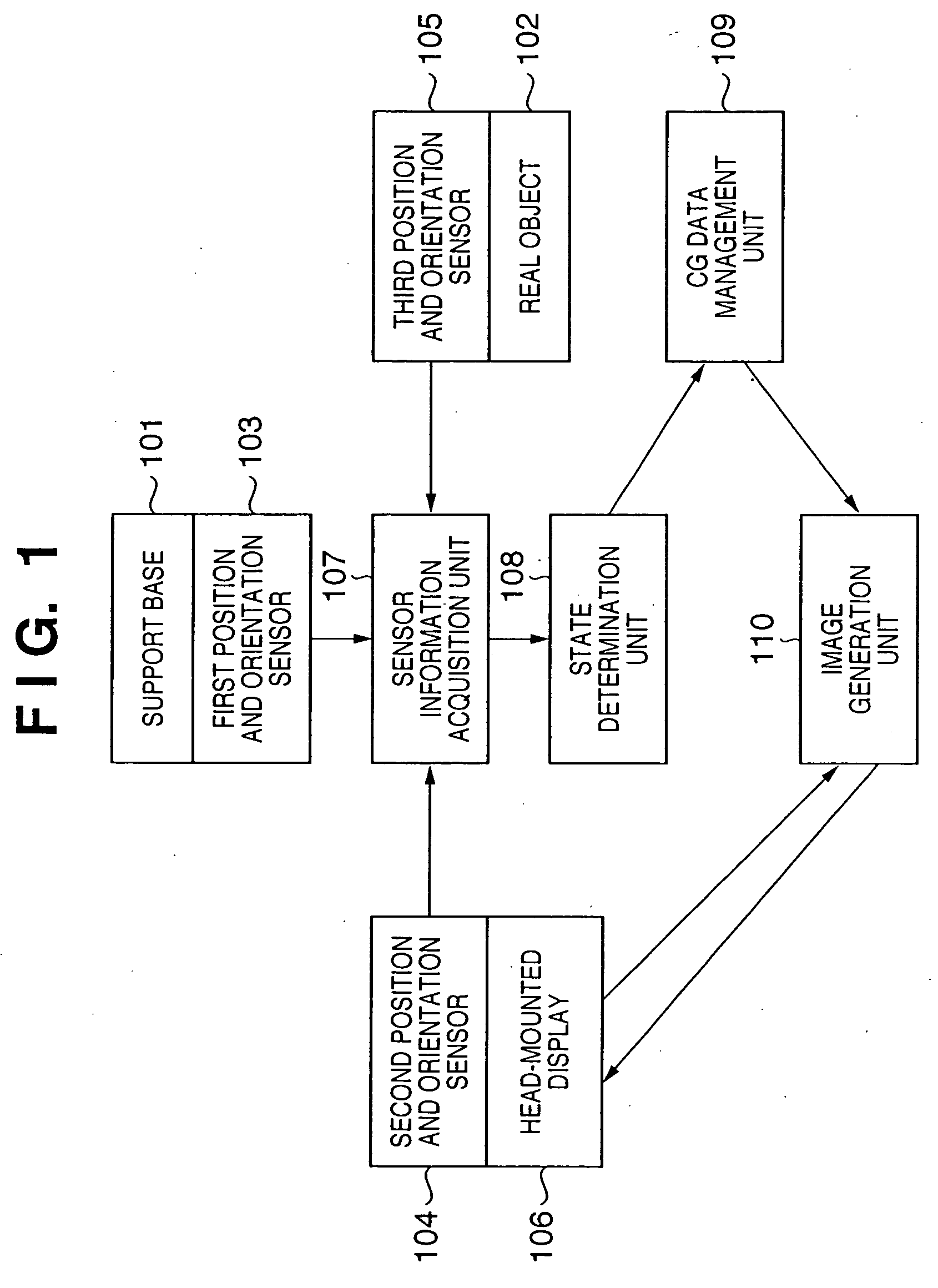
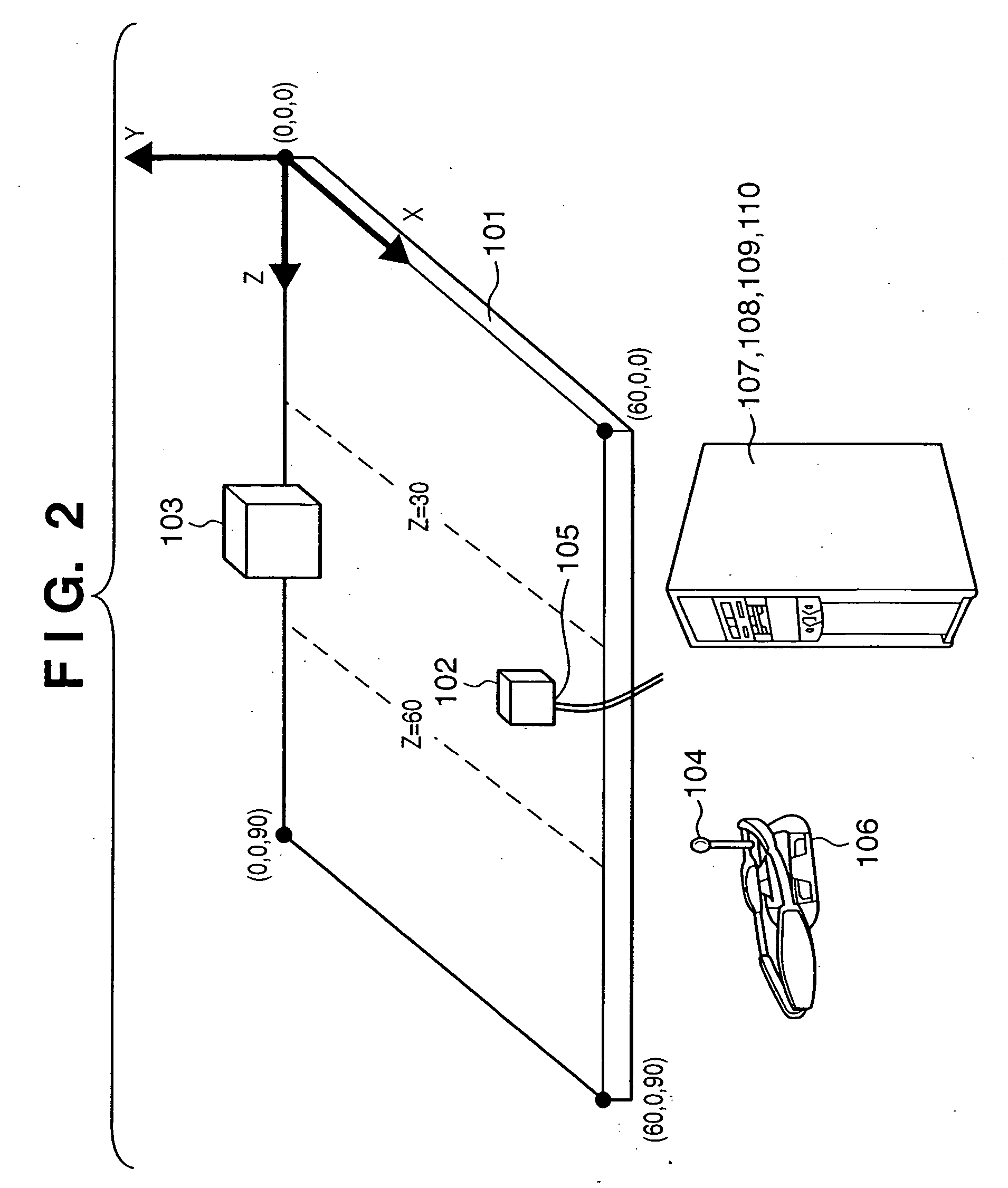
FIG. 1 is a block diagram showing an example of the arrangement of a 3D CG manipulation apparatus according to this embodiment. A support base 101 is not particularly limited as long as it can support a real object 102, and a wood table, rack, or the like may be used. The real object 102 is not particularly limited as long as it can have a position and orientation sensor 105. In this embodiment, a plastic cube is used.

First to third position and orientation sensors 103, 104, and 105 are respectively arranged on the support base 101, a head-mounted display 106, and the real object 102, and measure their relative pos...

Example

Second Embodiment

The second embodiment of the present invention will be described below with reference to the accompanying drawings. In this embodiment, a 3D CG manipulation apparatus and method for assembling simulation which allows the user to assemble virtual components superimposed on real objects will be explained.

The arrangement of the 3D CG manipulation apparatus of this embodiment is the same as that of the first embodiment, as has been explained using FIGS. 1 and 10. FIG. 9A depicts a use state of the 3D CG manipulation apparatus of this embodiment. In this embodiment, a second support base 301 is added to the arrangement shown in FIG. 2. The second support base 301 has a plastic rack shape with three shelves, and is fixed to the first support base 101. As shown in FIG. 9A, the side surface portions of the three shelves of the second support base 301 are respectively labeled by A, B, and C.

In this embodiment, it is checked based on the position and orientation of the ...

Example

Third Embodiment

A calibration method of a position and orientation sensor according to the present invention will be explained below taking an embodiment in which it is applied to a digital mock-up system exploiting the MR technique as an example.

A digital mock-up system according to this embodiment is a system that superimposes and presents a 3D CG image that represents a concrete shape and outer appearance of a given industrial product onto a simple mock-up (model) of that product using the MR technique. The system user can actually pick up and touch the mock-up while observing the mock-up superimposed with the 3D CG image of the product, and can virtually operate it.

The mock-up incorporates a position and orientation sensor. 3D CG data is generated in correspondence with the position and orientation of the mock-up detected from the measurement values of that sensor, and is superimposed on the mock-up. For this reason, the user can experience as if he or she were picking up ...


PUM


Abstract

A three-dimensional CG manipulation apparatus has a real object, a position and orientation sensor provided to the real object, a support base, a position and orientation sensor provided to the support base, a head-mounted display, a position and orientation sensor provided to the head-mounted display, a sensor information acquisition unit for acquiring information from the sensors, a state determination unit for determining the current state of the real object and support base, a CG data management unit for managing CG data to be displayed, and an image generation unit for generating an image to be displayed on the head-mounted display. In a mixed realty system that presents an image formed by superimposing a virtual CG image on a real object to the user, a manipulation such as replacement or the like can be easily made for the virtual CG image without interrupting the user's operation.

Description

FIELD OF THE INVENTION The present invention relates to a technique for superimposing and displaying an object (virtual object) in a virtual space rendered by CG onto a real space. BACKGROUND OF THE INVENTION A virtual reality (VR) system represents a three-dimensional computer graphics (3D CG) created by a computer to the user, thus allowing the user to experience a virtual space as if it were real. In recent years, a technique that presents information which is not available in the real world by compositing a 3D CG onto a video of the real world has been developed, and such technique is called an AR (Augmented Reality) system or MR (Mixed Reality) system. The AR system can superimpose a 3D CG onto a real object. For example, a game described in Japanese Patent Laid-Open No. 2000-353248 (reference 1) (corresponding U.S. Publication No.: 2002-072416) superimposes a 3D CG of a sword, weapon, or the like onto an interactive operation input device held by the user, thus allowing the...

Claims


Application Information

Patent Timeline
IPC IPC(8): G06T19/00
CPCG06T19/006
Inventor KUROKI, TSUYOSHIMATSUI, TAICHI
Owner CANON KK
Why Eureka
Try Eureka