Image adaptive deinterlacing method and device based on edge

a deinterlacing method and edge technology, applied in the field of digital video signal processing, can solve the problems of degrading picture quality, complicated construction, high price, etc., and achieve the effect of improving picture quality

Active Publication Date: 2005-04-07
SAMSUNG ELECTRONICS CO LTD
View PDF4 Cites 52 Cited by
  • Summary
  • Abstract
  • Description
  • Claims
  • Application Information

AI Technical Summary

Benefits of technology

It is a feature of the present invention to provide an image adaptive deinterlacing method and device based on an edge in which a picture quality is improved.

Problems solved by technology

Generally, the inter-field interpolation is known in the art as having excellent performance, but has a disadvantage in that construction is complicated and price is high due to an additional field memory that is needed for use of the inter-field information.
Since the Line Average of the intra-field interpolation performs the interpolation by using an average value of upper and lower-direction pixels, jagging occurs at a low gradient edge, thereby causing picture quality to be degraded.
However, the ELA cannot detect an actual edge and can erroneously detect a direction at a region having a vertical edge, at a region where the image is not distinct in brightness difference, and at a region having many high-frequency components of the image.
This causes the picture quality to be rather degraded due to the generation of a distinct erroneous high frequency component.
Even though the ELS has an excellent interpolation performance, the ELS has a tendency to be used, due to the above disadvantages, in an intra-field interpolation device using a recent popularized motion adaptive way than a separate deinterlacing device.
However, since much improvement is still required for the degradation of the picture quality, which is caused by erroneous interpolation, various ELSs are under development.

Method used


Image

  • Image adaptive deinterlacing method and device based on edge
  • Image adaptive deinterlacing method and device based on edge
  • Image adaptive deinterlacing method and device based on edge

Examples


Embodiment Construction

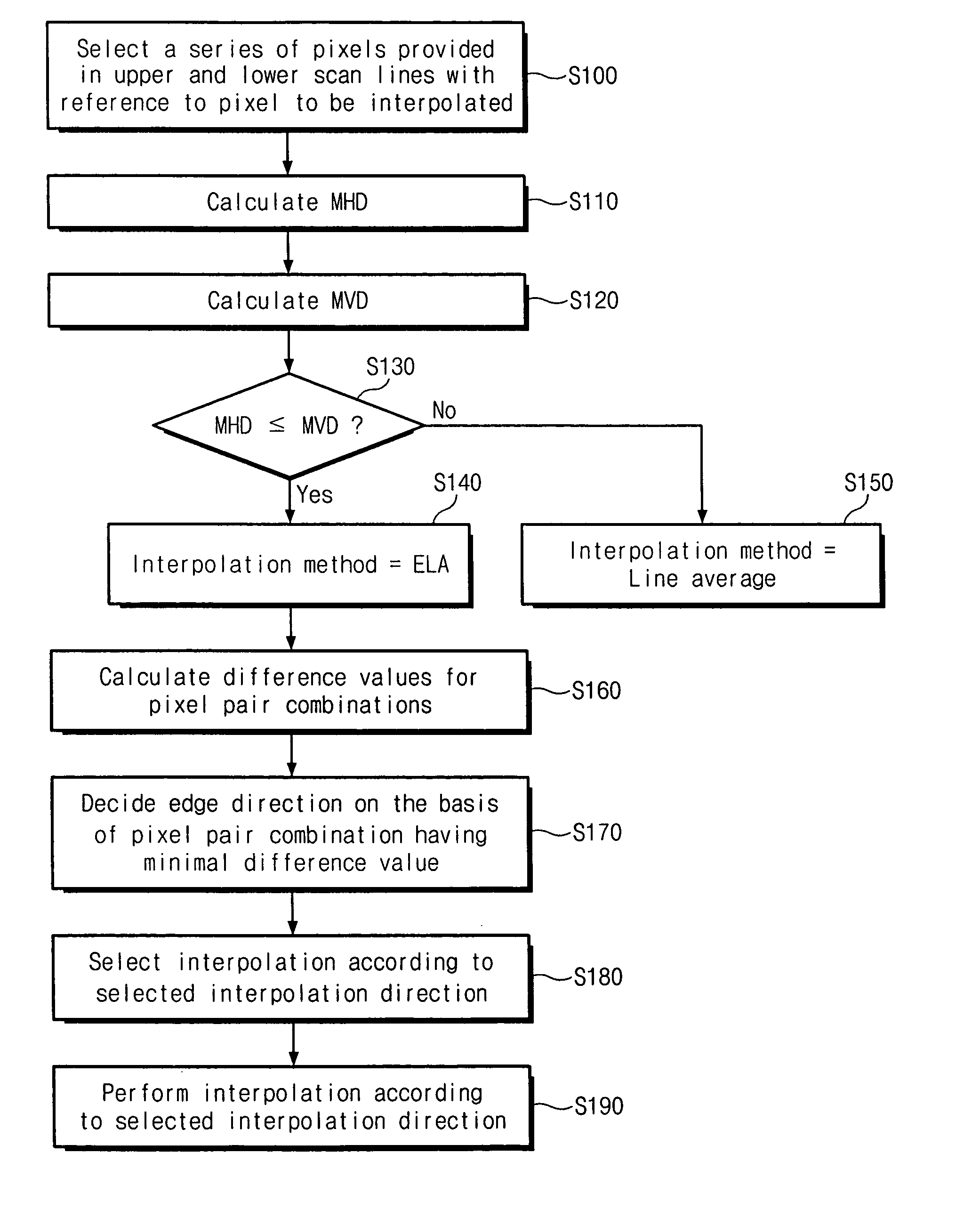
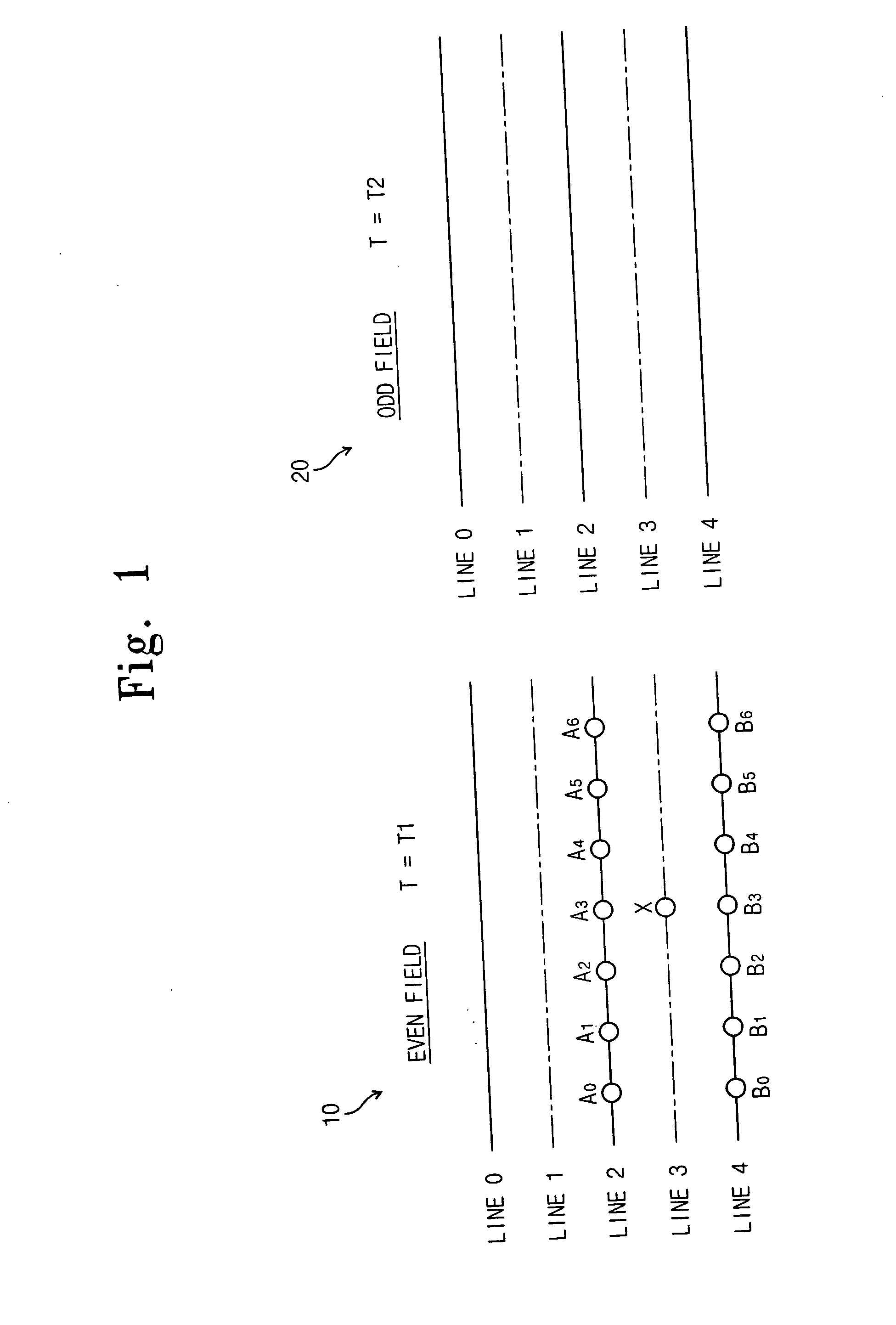
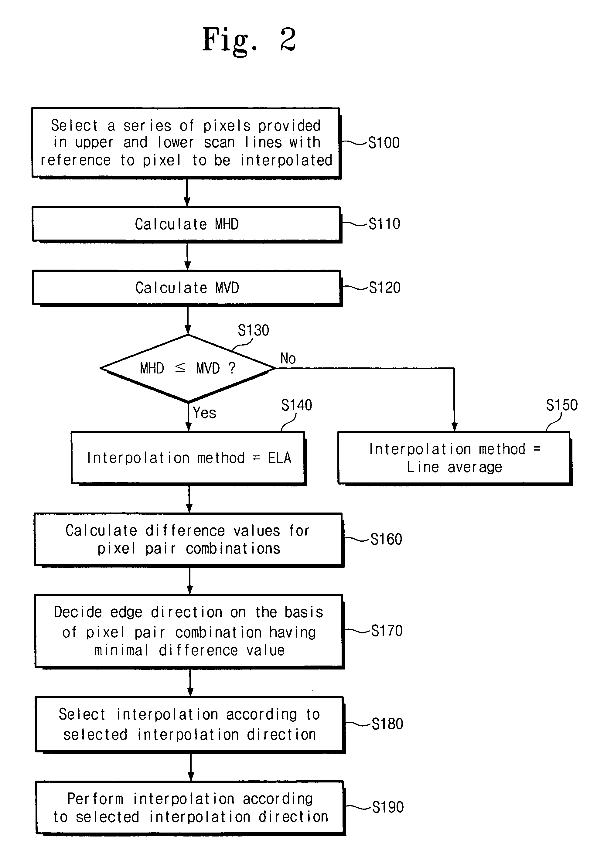
The present invention provides a deinterlacing device and method in which a field to be interpolated is divided into a low gradient edge region and a region having other characteristics and then, an ELA is applied at the low gradient edge region to minimize jagging and a Line Average is applied at another region to minimize error, thereby improving an entire picture quality. The present invention has stable performance by using a horizontal difference and a vertical difference, which are adaptive to an image characteristic at the time of dividing into two regions, in comparison with a conventional method using a fixed critical value. When the ELA is used to search a direction having a large similarity, the present invention obtains and averages maximal-numbered pixel difference values, which are available within the window, for respective directions, thereby preventing erroneous interpolation from being effected by a high frequency component. The present invention can not only be u...


PUM


Abstract

The present invention relates to a deinterlacing device and method for converting a video signal of an interlaced scan format into a video signal of a progressive scan format. The deinterlacing method including the steps of: measuring an edge gradient from a series of pixels provided in an upper scan line and a series of pixels provided in a lower scan line with reference to a pixel to be interpolated; determining an interpolation method on the basis of the measured edge gradient; calculating a difference value for each of pixel pair combinations, each of the pixel pair combinations having at least one pixel pair, the pixel pair having two pixels each one from each of the upper and lower scan lines with reference to the pixel to be interpolated, each of the pixel pair combinations having the pixel pairs that are adjacent to one another, the pixel pair combinations having different directions from one another; determining an edge direction on the basis of a direction of the pixel pair combination having the smallest difference value; and performing an interpolation for the pixel depending on the determined interpolation method and the determined edge direction.

Description

RELATED APPLICATION This application relies for priority on Korean patent application number 2003-68879, filed on Oct. 2, 2003, the contents of which are incorporated herein in their entirety by reference. BACKGROUND OF THE INVENTION 1. Field of the Invention The present invention relates to a digital video signal processing, and more particularly, to a deinterlacing device and method for converting a video signal of an interlaced scan format into a video signal of a progressive scan format. 2. Description of the Related Art Deinterlacing is typically classified as intra-field interpolation using spatial correlation or inter-field interpolation using intra-field information and inter-field information on the basis of the spatial correlation and temporal correlation to perform interpolation. The intra-field interpolation uses only the intra-field information on the basis of the spatial correlation to perform the interpolation, and is represented as a line repetition, a line aver...

Claims


Application Information

Patent Timeline
Patent Type & Authority Applications(United States)
IPC IPC(8): H04N5/44H04N7/01
CPCH04N7/012H04N7/0142H04N7/0135H04N7/01
Inventor JI, EUN-SEOKJUNG, YONG-JOON
Owner SAMSUNG ELECTRONICS CO LTD
Why Eureka
Try Eureka