Flat panel display and panel module thereof

a technology of flat panel display and panel module, which is applied in the direction of instruments, portable computer details, and electric apparatus casings/cabinets/drawers, etc., can solve the problems of compromising the object of a narrow frame profile, affecting the productivity of the display, and affecting the appearance of the display. , to achieve the effect of improving productivity and efficiency, and reducing the thickness of the rear fram

Inactive Publication Date: 2005-04-07
QUISDA CORP
View PDF4 Cites 8 Cited by
  • Summary
  • Abstract
  • Description
  • Claims
  • Application Information

AI Technical Summary

Benefits of technology

[0040] At least a part of the connecting portion is disposed on the receiving portion and partly disposed on the back thereof. As a result, there is no need to rotate the panel, with direct assembly of the bracket and the panel from the rear provided. Thus, productivity and efficiency are greatly improved. Moreover, the rear frame is connected to the main bracket by the connecting portion. Because this connecting portion is partly disposed on the receiving portion or partly extends to back thereof, the connecting portion reduces thickness of the rear frame.
[0041] Thus, the flat panel display and panel module thereof provides better productivity.

Problems solved by technology

Although design may provide a narrow frame structure (with frame thickness d as narrow as possible), the assembling process is complicated.
As a result, the object of a narrow frame profile is compromised.
Similar problems occur in other types of flat panel displays.

Method used


Image

  • Flat panel display and panel module thereof
  • Flat panel display and panel module thereof
  • Flat panel display and panel module thereof

Examples


first embodiment

[0055] First embodiment

[0056]FIG. 3 is an exploded view of a liquid crystal display according to a first embodiment of the present invention. The liquid crystal display includes a housing 50 and a panel module 60. The housing 50 has a front cover 501 and a rear cover 502, housing the panel module 60 therein.

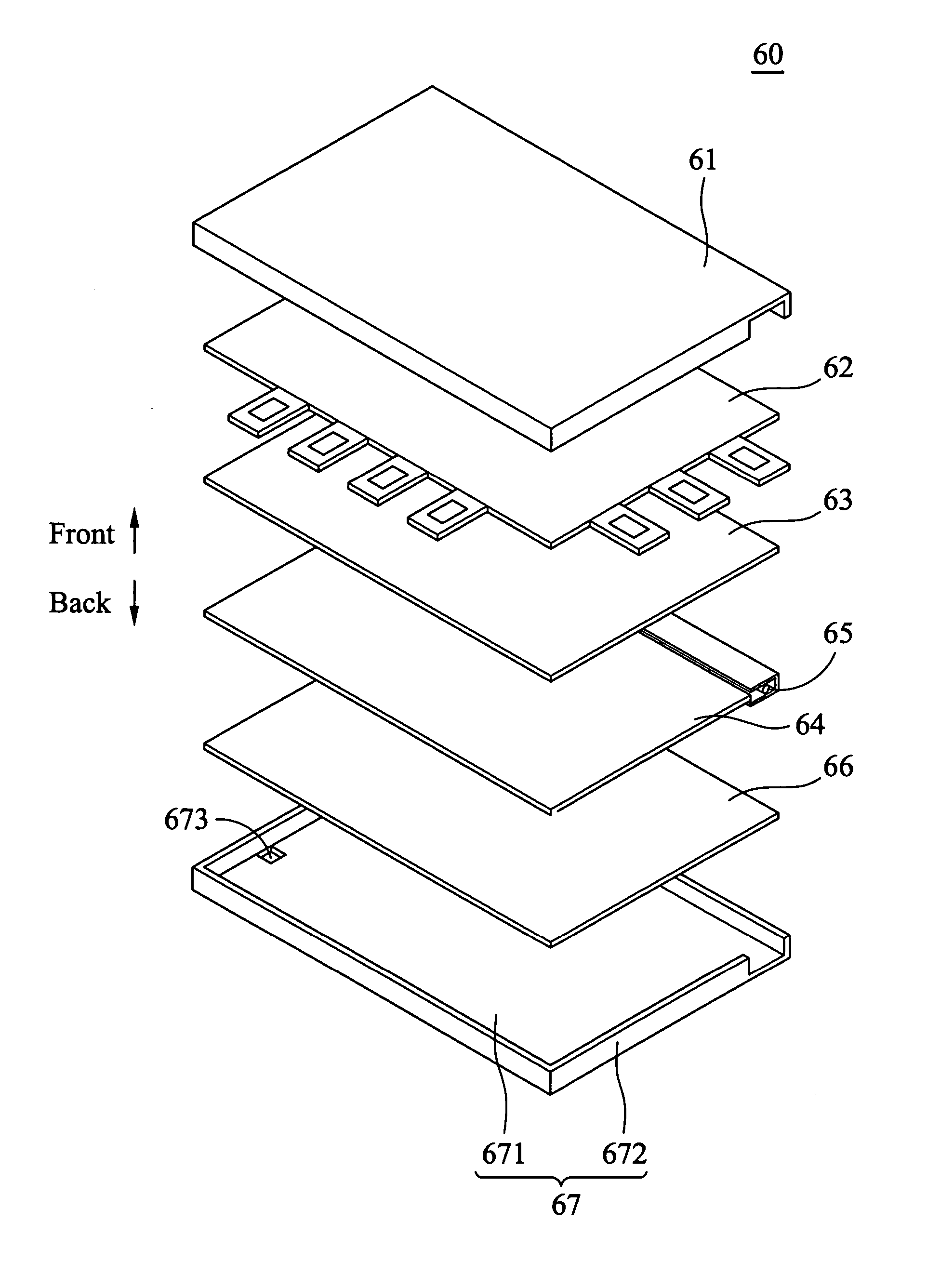
[0057] A plurality of screw holes (not shown in FIG. 3, but described subsequently) are positioned on a rear side of the panel module 60 so that screws 84 directly fix the panel module 60 to the rear cover 502 from the rear side of the panel module 60. The panel module 60 does not need to be rotated during assembling process of the liquid crystal display, thus increasing speed of assembly.

[0058] In addition, another advantage of the present invention is provision of a narrow frame described subsequently.

[0059]FIG. 4 is an exploded view of the panel according to a first embodiment of the present invention. The panel module 60 has a front frame 61 and a rear frame 67. A panel 62...

second embodiment

[0067] Second embodiment

[0068]FIG. 7 is a perspective exploded view of a liquid crystal display according to a second embodiment of the present invention. The symbols of the second embodiment are identical to those of the first embodiment, and thus explanation is omitted here. In the second embodiment, a main bracket 70 is introduced. The panel module 60 is secured to the rear cover 502 of the housing 50 by this main bracket 70. Specifically, a screw 81 fixes the connecting portion 673, 674, 675, or 676 of the panel module 60 to the main bracket 70, further engaged with the rear cover 502 by screw 82. It should be noted that the screws 81 and 82 are disposed in different locations of the main bracket 70. Moreover, the screw 81 is closer to two sides of the main bracket 70 than the screw 82. As a result, the screw 81 and the connecting portions 673, 674, 675, or 676 are connected closer to the peripheral portion 672, providing enhanced structural strength.

[0069] In conclusion, the p...


PUM

PropertyMeasurementUnit
distanceaaaaaaaaaa
thicknessaaaaaaaaaa
speedaaaaaaaaaa

Abstract

A flat panel display and panel module thereof. The flat panel display includes a housing, a panel module and a main bracket. The panel module, contained in the housing, includes a front frame, a rear frame, and a panel. The front frame and the rear frame are assembled to encase the panel. The rear frame has at least one connecting portion, covered by the encased panel. The main bracket is disposed in the housing to connect the housing and the connecting portion of the rear frame.

Description

BACKGROUND OF THE INVENTION [0001] 1. Field of the Invention [0002] The present invention relates to a flat panel display and panel module thereof, and in particular to a flat panel display with a narrow frame creating better production efficiency. [0003] 2. Description of the Related Art [0004] Flat panel displays comprise passive and active matrix display technologies. Liquid crystal display (LCD) is a common type of passive matrix display (PMLCD), and active matrix display includes plasma display panels (PDP), light emitting diodes (LED), vacuum fluorescent displays (VFD), electroluminescent displays (ELD), field emission displays (FED), and others. [0005] U.S. Pat. No. 5,835,139, as shown in FIG. 1, provides a liquid crystal display device. The liquid crystal display includes a housing 10 (made of plastic) and a panel module 20. The housing 10 has a front cover 101 and a rear cover 102, with the panel module 20 disposed therebetween. The covers 101, 102 not only protect the pane...

Claims


Application Information

Patent Timeline
Patent Type & Authority Applications(United States)
IPC IPC(8): G02F1/13G02F1/133G02F1/1333G06F1/16
CPCG02F1/133308G02F2001/133325G02F2201/46G06F2200/1612G06F1/1616G06F1/1637G06F1/1601G02F1/133325
Inventor TSUO, CHUN-TUNGYEN, CHING-HUI
Owner QUISDA CORP
Why Eureka
Try Eureka