

Lens holder and lens protector for use in optical pick-up and method of manufacturing same
a technology for optical pick-up and lens protector, which is applied in the direction of instruments, disposition/mounting of heads, other domestic objects, etc., can solve the problems of short clearance between the objective lens and the disc surface, inability to correctly read information, and small work space, etc., and achieve high dimensional accuracy
Inactive Publication Date: 2005-04-07
NTN CORP
View PDF11 Cites 10 Cited by
- Summary
- Abstract
- Description
- Claims
- Application Information
AI Technical Summary
Benefits of technology
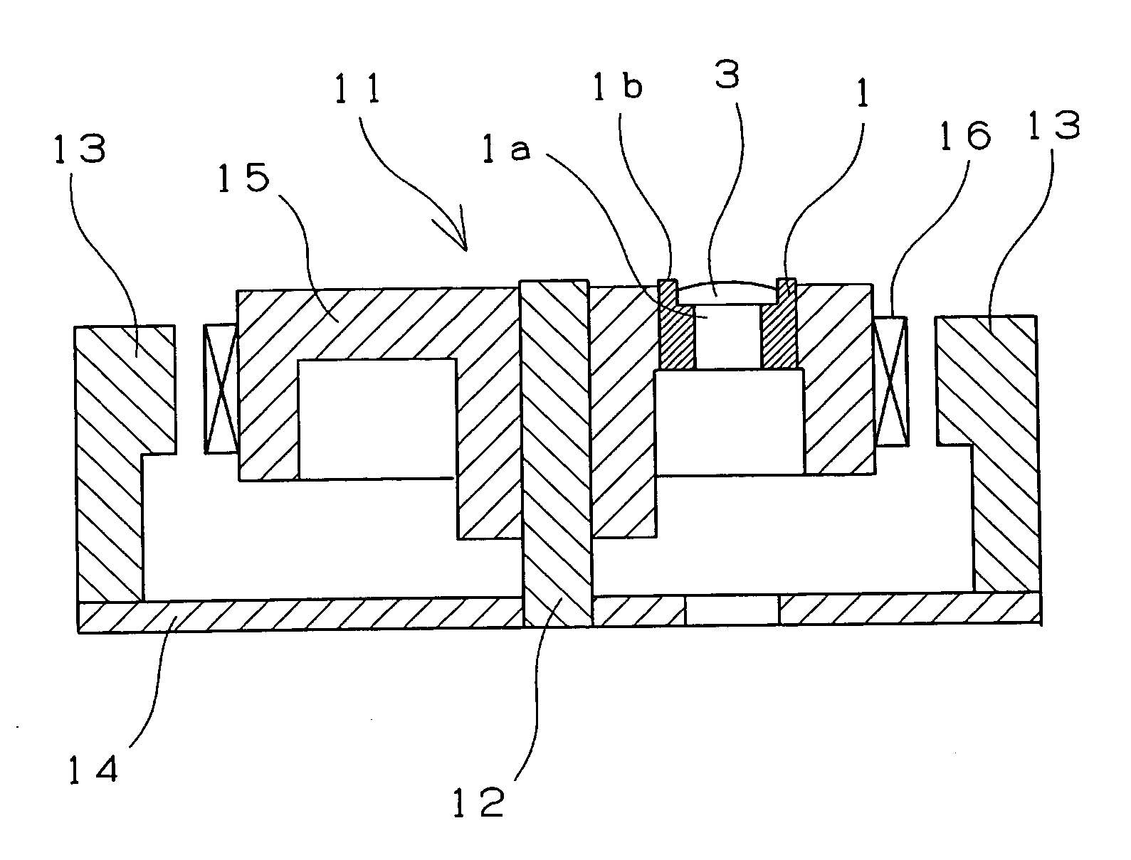
[0014] Since the contact portion which contacts the ejector pin is not formed on the lens holder nor on the lens protector, less burrs are formed on the surface thereof. The gate mark is not formed on the surface of the lens holder and the lens protector confronting the optical disc. Therefore no burrs are formed on the surface of the lens holder and the lens protector confronting the optical disc. Thus excellent flatness (JIS B 0182) can be kept thereon. Consequently even though the lens holder and the lens protector contact the optical disc, the surface of the optical disc is not damaged. And, the surface of the lens holder and the lens protector can be coated easily with a film.
[0016] In the process of projecting the molded product from the cavity, the lens holder and the boss can be reliably projected from the cavity by means of the ejector pin in a favorable balance. In addition the flow distribution of melted resin is uniform when the melted resin is filled into the cavity. Thereby the lens-mounting hole has high dimensional accuracy.
Problems solved by technology
If there is a deviation (radial deviation of optical axis) between a signal track (bit string of information) on the disc and the optical axis of the objective lens, information cannot be correctly read.
Because the capacity and density of an optical disc has increased greatly in recent years, a work space has become small.
That is, the clearance between the objective lens and the disc surface has become short when a focus servo is in operation.
Consequently the danger of a collision between the objective lens and the optical disc has increased.
Therefore the conventional optical pick-up has a problem that owing to the collision between the objective lens and the optical disc, the signal-recording layer of the optical disc is liable to be damaged.
Powder generated from the burrs are scattered in the apparatus such as the CD-ROM, thus damaging the optical disc or causing a failure.
However, the barrel polishing has a problem that an objective lens-mounting hole and a bearing hole are liable to be clogged with media.
When the lens holder is formed by injection molding, it has an unfavorable surface configuration on the periphery of the gate.
Method used
View moreImage
Smart ImageViewing Examples

Examples
examples
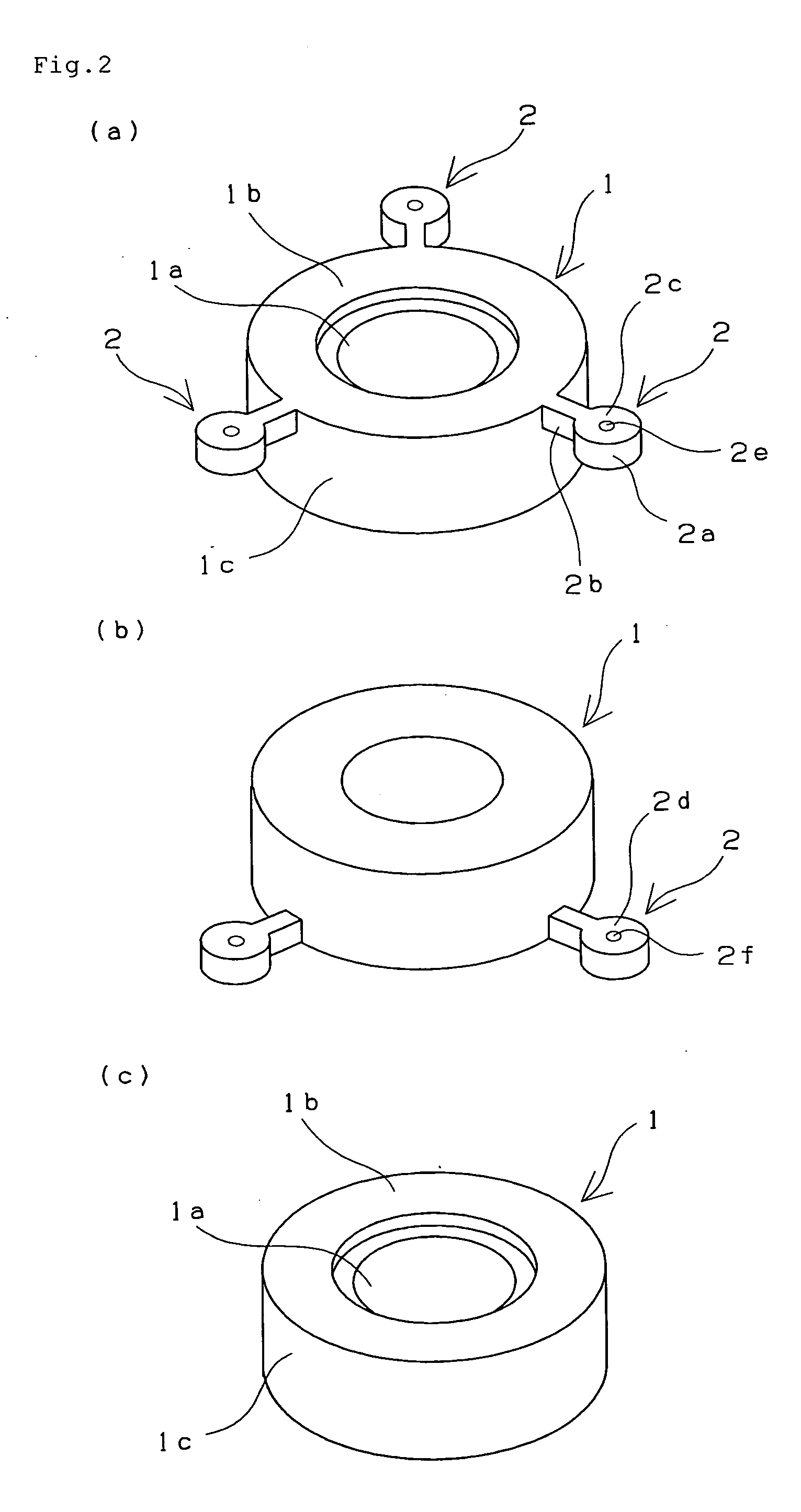
[0049] A lens holder, of an optical pick-up, having the configuration shown in FIG. 2C was formed by injection-molding LCP (Bectra A230 containing 30 wt % of carbon fiber produced by Polyplastics Inc.).
[0050] Burrs were present on a cut mark of the boss and on parting lines formed on the lens holder from which bosses were removed. The surface of the lens holder confronting the optical disc had a flatness of 0.3 to 1.7 μm. It took 25 seconds to perform barrel polishing.
Login to View More PUM
| Property | Measurement | Unit |
|---|---|---|
| flatness | aaaaa | aaaaa |
| flatness | aaaaa | aaaaa |
| optical axis | aaaaa | aaaaa |
Abstract
The present invention provides a lens holder and a lens protector having little burrs and no gate marks formed on a surface thereof confronting an optical disc and a method of manufacturing the lens holder and the lens protector. The lens holder is formed in integration with a boss by injection-molding and has a hole capable of holding an objective lens on a surface of the lens holder confronting an optical disc. The boss having a gate and a contact portion which contacts a ejector pin is formed on a peripheral side surface of the lens holder when the injection molding is performed and cut off from the lens holder after the injection molding finishes.
Description
BACKGROUND OF THE INVENTION [0001] The present invention relates to a lens holder and a lens protector for use in an optical pick-up. [0002] As optical information-recording media, a CD-ROM, a CD-R, a CD-RW, a DVD-ROM, and a DVD-RW are known. The optical pick-up of these apparatuses for performing a focus control and a tracking control detects information by converging light beams which have passed through an objective lens on a disc surface. Thus to form an image on the disc surface, it is necessary to focus the light beams thereon by compensating defocusing caused by deflection of the disc. If there is a deviation (radial deviation of optical axis) between a signal track (bit string of information) on the disc and the optical axis of the objective lens, information cannot be correctly read. Thus it is necessary to make the optical axis of the objective lens coincident with the signal track by compensating the deviation of the signal track. [0003] Because the capacity and density o...
Claims
Login to View More Application Information
Patent Timeline
 Patent Type & AuthorityApplications(United States)
IPC IPC(8): B29C45/38B29L11/00G02B7/02G11B7/09G11B7/12G11B7/121G11B7/135G11B7/22G11B17/00G11B21/16
CPCG11B7/1201G11B7/0935G11B7/121Y10S425/808
InventorTAKEO, KATSUSHIGOTO, KEIICHIFUKUZAWA, SATORU
OwnerNTN CORP