Ejector, fine solid piece recovery apparatus and fluid conveyor

a recovery apparatus and fluid conveyor technology, applied in conveyors, conveyors, transportation and packaging, etc., can solve the problems of affecting the cutting operation affecting the flow rate of fluid conveyors, etc., to improve the conveying efficiency, increase the ejector power, and increase the negative pressure

Inactive Publication Date: 2005-04-07
TRINITY IND CORP
View PDF8 Cites 33 Cited by
  • Summary
  • Abstract
  • Description
  • Claims
  • Application Information

AI Technical Summary

Benefits of technology

[0018] According to the experiment made by the inventors, the flow speed of a fluid sucked from the suction port reaches a high speed at the junction point with a jet stream, but the distance of the high speed region is short in a case where pressure control holes are not present. On the contrary, when the pressure control holes are formed as in the feature of the present invention, it has been confirmed that the distance of the high speed region is made longer and, as a result, the flow speed and the flow rate of the fluid sucked from the suction port are increased.
[0026] Further, since the atmospheric pressure is lower than the static pressure of the jet stream, the static pressure can be caused to escape and, accordingly, the negative pressure of the ejector is increased to increase the ejector power.
[0031] With the feature described above, even in a case of using a convergent-divergent nozzle of a relatively large inner diameter, since the jet stream can be forced to the center of the convergent-divergent nozzle to form a high speed region at the center, the flow speed and the flow rate of the suction stream can be increased to increase the negative pressure of the ejector and increase the ejector power.
[0033] In accordance with the fifth feature of the present invention, since the negative pressure of the ejector is high, the conveying air stream formed with the negative pressure of the ejector can suck even fine solids such as relatively heavy metal cuttings and, when they are caused to flow into the cyclone separator, the energy of the stream forms a swirling stream in the cylindrical separation column in which air gathered to the center is exhausted to the outside, and the fine solids are collided against the circumferential wall centrifugally and dropped, and sucked fine solids can be recovered easily.
[0034] According to a sixth feature of the present invention, since an ejector of high negative pressure is used as a driving source for a fluid conveyor, even a liquid of high specific weight such as burnt ashes or sludge-like liquid wastes can also be conveyed reliably.

Problems solved by technology

In this case, since a great amount of cuttings are discharged, if left as they are, they not only hinder the cutting operation but also twine around the works or machine tools under rotation, to injure the works or scatter the cuttings to the surroundings.
The recovered cutting oils are circulated and re-utilized but they have to be disposed finally as industrial wastes which is not desirable in view of environmental protection.
However, since individual belt conveyors constitutes each a linear conveying path, when a plurality of belt conveyors are connected, the conveying paths are formed in a polygonal line which makes a free layout difficult and increases the installation cost, as well as gives rise to a problem of increasing the running cost since individual conveyors require driving motors respectively.
Further, it also involves a problem of tending to cause failure when fine cuttings and the likes clog the mechanical driving portion of the belt conveyor.
However, when a mechanical vacuum pump is used as a driving source for the pneumatic conveyor, it also requires increased installation cost and running cost and there is also a worry that cuttings clog the vacuum pump.
However, since the ejector has an extremely low negative pressure compared with the reciprocal, rotational or centrifugal mechanical vacuum pump, although it may be used as a driving source for a pneumatic conveyor that conveys light-weight material such as powder, it can not be practical as a driving source for a pneumatic conveyor that conveys fine metal pieces such as cuttings.

Method used


Image

  • Ejector, fine solid piece recovery apparatus and fluid conveyor
  • Ejector, fine solid piece recovery apparatus and fluid conveyor
  • Ejector, fine solid piece recovery apparatus and fluid conveyor

Examples


Embodiment Construction

[0042] The present invention is to be described specifically by way of its preferred embodiments with reference to the drawings.

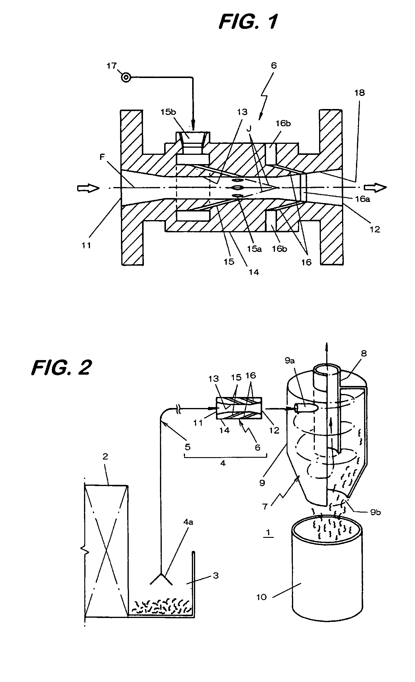
[0043] In fine solid recovery apparatus 1 according to the present invention, as shown in FIG. 2, metal cuttings (fine solids) sucked from a bucket 3 provided to a machine tool 2 are conveyed by a pneumatic conveyor 4 and then recovered.

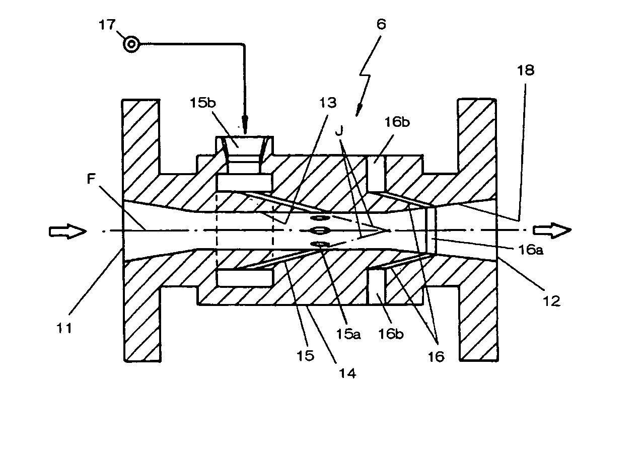
[0044] In a conveying pipeline 5 for the pneumatic conveyor 4, an ejector 6 forming a conveying air stream is intervened in which one line end is formed as a suction end 4a and the other line end as a discharge end 4b is connected to a cyclone separator 7.

[0045] The cyclone separator 7 has a hopper-type cylindrical separation column 9 having an exhaust cylinder 8 formed at the center. The cylindrical separation column 9 has a flow inlet 9a formed to an upper part thereof being opened in the tangential direction at the inner circumferential surface, and a recovery port 9b for dropping the cuttings formed at the bottom of t...


PUM


Abstract

An ejector capable of generating a high negative pressure capable of sucking and conveying fine metal pieces such as cuttings, for example, in a case of using the ejector as a driving source for a fluid conveyor, comprising a convergent-divergent nozzle having a throat formed between a suction port and a discharge port in which jet blowing holes are formed in the convergent-divergent nozzle for jetting a jet stream from the upstream to the downstream of the throat thereby forming a negative pressure, wherein pressure control holes are formed being opened to the downstream of the jet blowing holes for communicating a pressure space at a level higher than a negative pressure formed by the jet stream and lower than a static pressure of the jet stream and the inside of the convergent-divergent nozzle.

Description

BACKGROUND OF THE INVENTION [0001] 1. Field of the Invention [0002] The present invention concerns an ejector for sucking a fluid by utilizing a negative pressure formed by the involving effect of a jet stream jetted at a high speed, a fine solids recovery apparatus using the ejector and a fluid conveyor. [0003] 2. Statement Related Art [0004] In recent years, numerical control (NC) systems have been progressed in machine tools for cutting metal works and most of processes from setting of works and machine tools to the completion of the cutting operation have been conducted automatically. [0005] In this case, since a great amount of cuttings are discharged, if left as they are, they not only hinder the cutting operation but also twine around the works or machine tools under rotation, to injure the works or scatter the cuttings to the surroundings. [0006] In view of the above, it has been adopted, upon cutting works, a method of flowing cuttings together with lubricants and cutting o...

Claims


Application Information

Patent Timeline
Patent Type & Authority Applications(United States)
IPC IPC(8): B65G53/14B65G53/58
CPCB65G53/58B65G53/14
Inventor MOROHASHI, YASUOOMORI, HIDETOSHINARUSE, TOSHIHIRO
Owner TRINITY IND CORP
Why Eureka
Try Eureka