Ultrasonic transmission/reception apparatus

a transmission/reception apparatus and ultrasonic technology, applied in ultrasonic/sonic/infrasonic image/data processing, instruments, applications, etc., can solve the problems of inability to image the interior of the bone, the size of the opening is limited to a certain size, and the azimuth resolution degrades, etc., to achieve high resolution

Inactive Publication Date: 2005-04-07
FUJIFILM HLDG CORP +1
View PDF4 Cites 33 Cited by
  • Summary
  • Abstract
  • Description
  • Claims
  • Application Information

AI Technical Summary

Benefits of technology

The present invention has for its object to provide an ultrasonic transmission / reception apparatus which can image both a minute tissue around a bone part in an object to be inspected and a minute tissue inside the bone, at a high resolution.

Problems solved by technology

On the other hand, the size of the opening is limited to a certain size in relation to the size of the object.
Therefore, when an ultrasonic wave of low frequency is employed in order to image the deep part of the object, the azimuth resolution degrades, and hence, the minute structure of the deep part such as the interior of a bone cannot be imaged.
As a result, the distance resolution of detection data on the outer side of a bone part, namely, the shallow part of the object degrades drastically.

Method used


Image

  • Ultrasonic transmission/reception apparatus
  • Ultrasonic transmission/reception apparatus
  • Ultrasonic transmission/reception apparatus

Examples


first embodiment

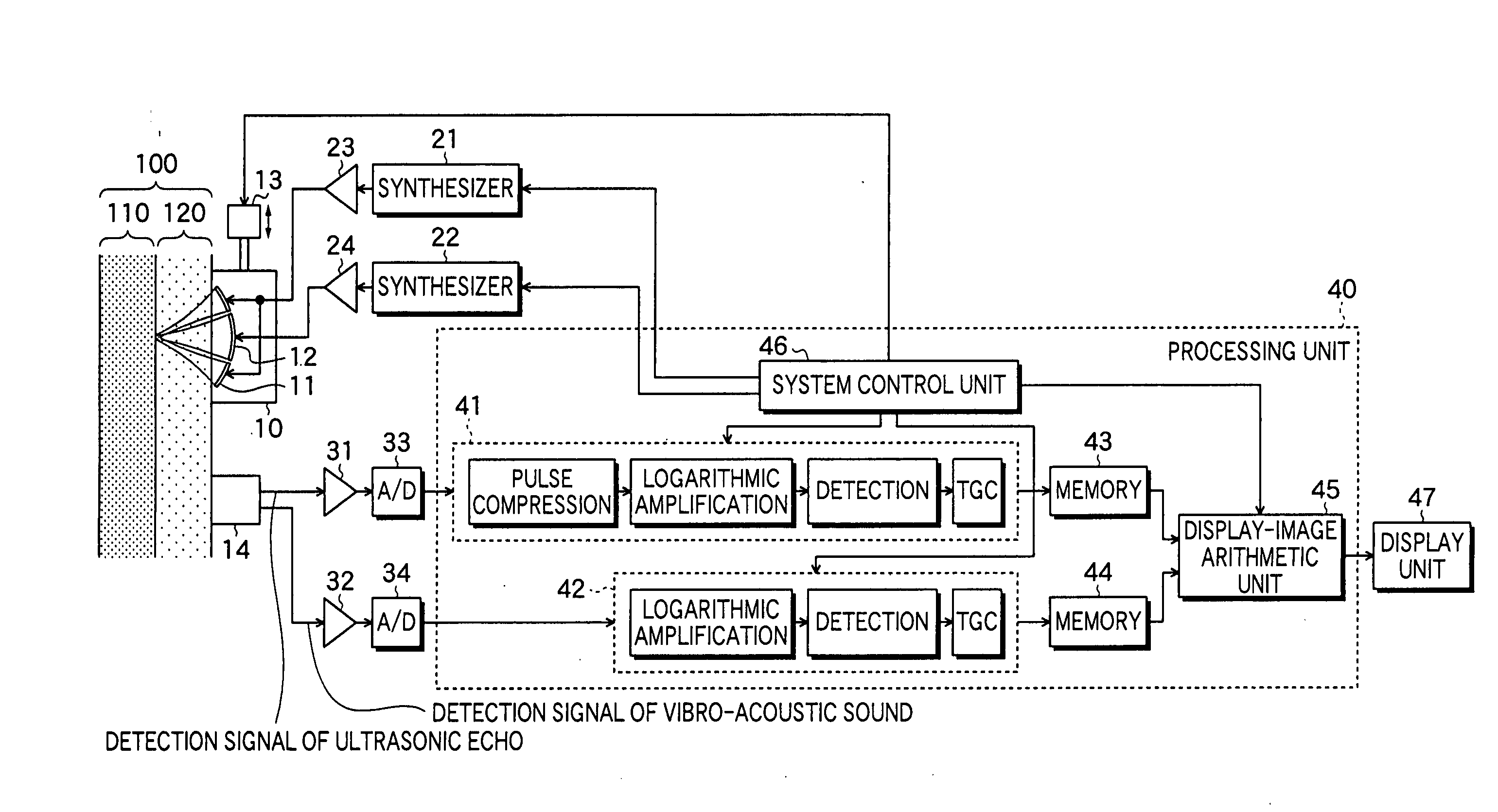
FIG. 1 is a block diagram showing the configuration of an ultrasonic transmission / reception apparatus according to the invention. The ultrasonic transmission / reception apparatus is an apparatus which transmits ultrasonic waves and receives ultrasonic echoes from an object to be inspected so as to image the ultrasonic echoes, and which generates vibro-acoustic sounds in the object and receives the vibro-acoustic sounds so as to image the vibro-acoustic sounds.

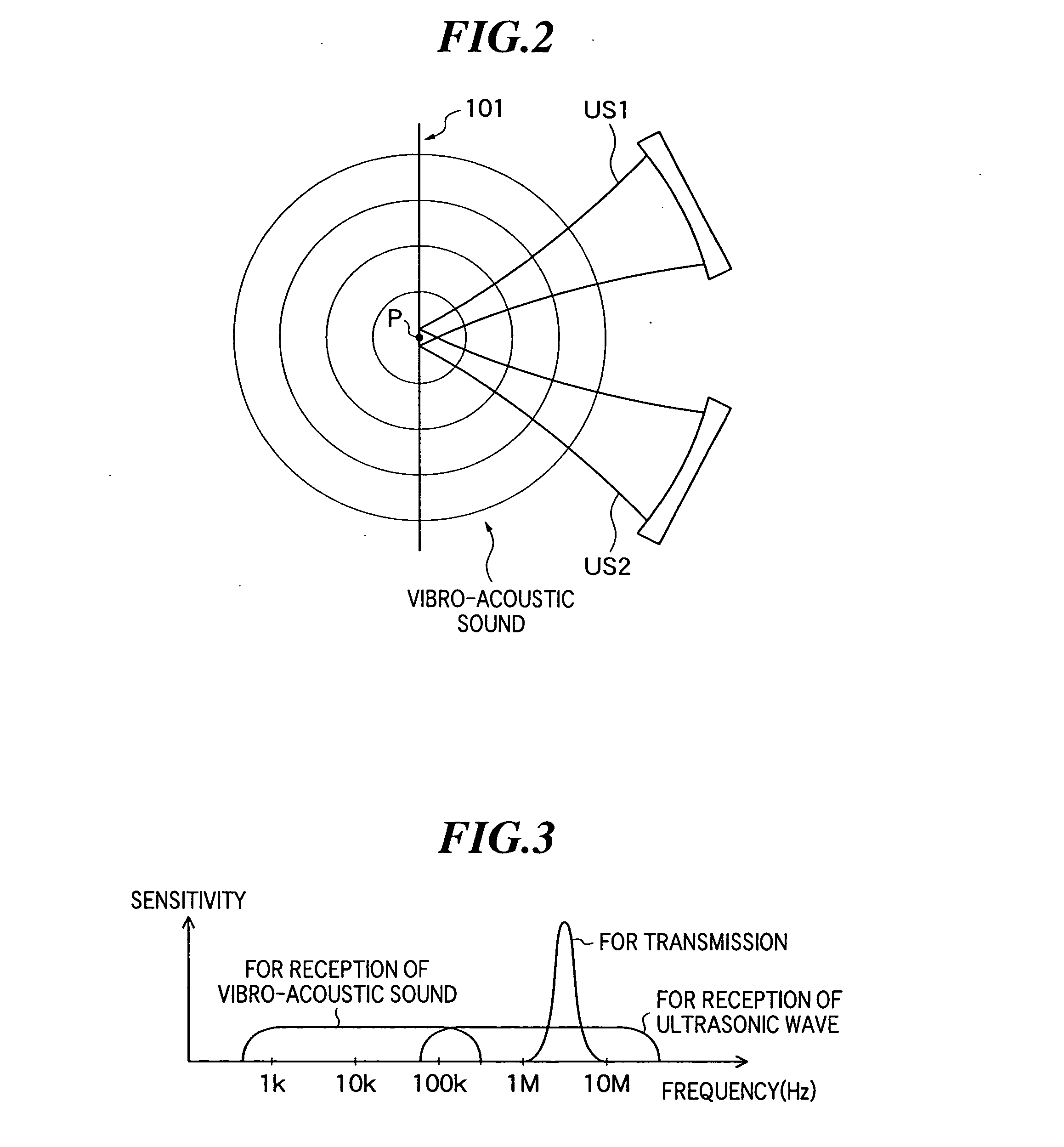
First, the vibro-acoustic sound will be explained. As shown in FIG. 2, when two ultrasonic beams US1 and US2 whose frequencies are slightly different are transmitted toward an object 101, vibration occurs in a region P irradiated with the two ultrasonic waves (this phenomenon is also termed “vibro-acoustic phenomenon”). The vibration generates an acoustic wave (or ultrasonic wave) called “vibro-acoustic sound”. The wave fronts of the vibro-acoustic sound are depicted in FIG. 2. The vibro-acoustic sound has a frequency (in, for ...

second embodiment

Next, an ultrasonic transmission / reception apparatus according to the invention will be described.

The ultrasonic transmission / reception apparatus according to this embodiment shown in FIG. 9 has a reception unit 16 which is mechanically connected with an ultrasonic transmission unit 10. The remaining configuration is the same as in the ultrasonic transmission / reception apparatus shown in FIG. 1.

Here, the intensity of a vibro-acoustic sound generated in the object represents the property of a region where the vibro-acoustic sound has been generated. However, the vibro-acoustic sound attenuates during its propagation within the object, likewise to an ultrasonic wave. Accordingly, when the positional relationship between the generation region of the vibro-acoustic sound and the reception unit changes, the attenuation rate of the vibro-acoustic sound changes, and hence, the precision of information on the vibro-acoustic sound generation region lowers.

In the ultrasonic transmission / ...

third embodiment

Next, an ultrasonic transmission / reception apparatus according to the invention will be described.

The ultrasonic transmission / reception apparatus shown in FIG. 10 includes an ultrasonic transmission / reception unit 17 which transmits and receives ultrasonic waves, transmission / reception changeover units 20, and a reception unit 50 which receives a vibro-acoustic sound, instead of the ultrasonic transmission unit 10 and reception unit 16 shown in FIG. 9. The ultrasonic transmission / reception unit 17 includes ultrasonic transducers 18 and 19 as elements which both transmit ultrasonic waves and receive ultrasonic echoes. The remaining configuration is the same as in the ultrasonic transmission / reception apparatus shown in FIG. 9.

The ultrasonic transducers 18 and 19 transmit the ultrasonic waves having frequencies different from each other, respectively, thereby to generate a vibro-acoustic sound, and they receive the ultrasonic echoes generated by the reflections of the ultrasonic wa...


PUM


Abstract

An ultrasonic transmission/reception apparatus which can image both a minute tissue around a bone part in an object and a minute tissue inside the bone, at a high resolution. The apparatus includes a system control unit which controls the synthesizers so that a first ultrasonic wave may be transmitted from one of the transmission elements while its frequency is being swept, and that a second ultrasonic wave may be transmitted from the other transmission element while its frequency is being swept with a predetermined difference frequency held relative to the frequency of the first ultrasonic wave, a signal processing unit which subjects the detection signal of the ultrasonic echo to predetermined signal processing, a signal processing unit which subjects the detection signal of the vibro-acoustic sound to predetermined signal processing, and a display-image arithmetic unit which generates B-mode image data based on the detection signals subjected to the signal processing.

Description

BACKGROUND OF THE INVENTION 1. Field of the Invention The present invention relates to an ultrasonic transmission / reception apparatus for use in, for example, making the diagnoses of the internal organs of living bodies by transmitting and receiving ultrasonic waves. 2. Description of a Related Art In the field of medical treatment, a variety of image technologies have been developed in order to make diagnoses by observing the inner parts of objects to be inspected. Among them, ultrasonic imaging which acquires the internal information of the object by transmitting and receiving ultrasonic waves does not involve exposure to radiation, unlike the other medical image technologies such as X-ray photography and RI (Radio Isotope) scintigraphy. Therefore, the ultrasonic imaging is utilized for a foetus diagnosis in an obstetrical region, and in extensive regions including a gynecological region, a circulatory system, a digestive system, etc., as the image technology of high safety. ...

Claims


Application Information

Patent Timeline
Patent Type & Authority Applications(United States)
IPC IPC(8): G01B17/00A61B8/00A61B8/08G01B17/06G01S7/52G01S7/524G01S15/89
CPCA61B8/0875A61B8/4483G01S15/8961G01S15/895G01S7/52038
Inventor SATOH, TOMOO
Owner FUJIFILM HLDG CORP
Why Eureka
Try Eureka