

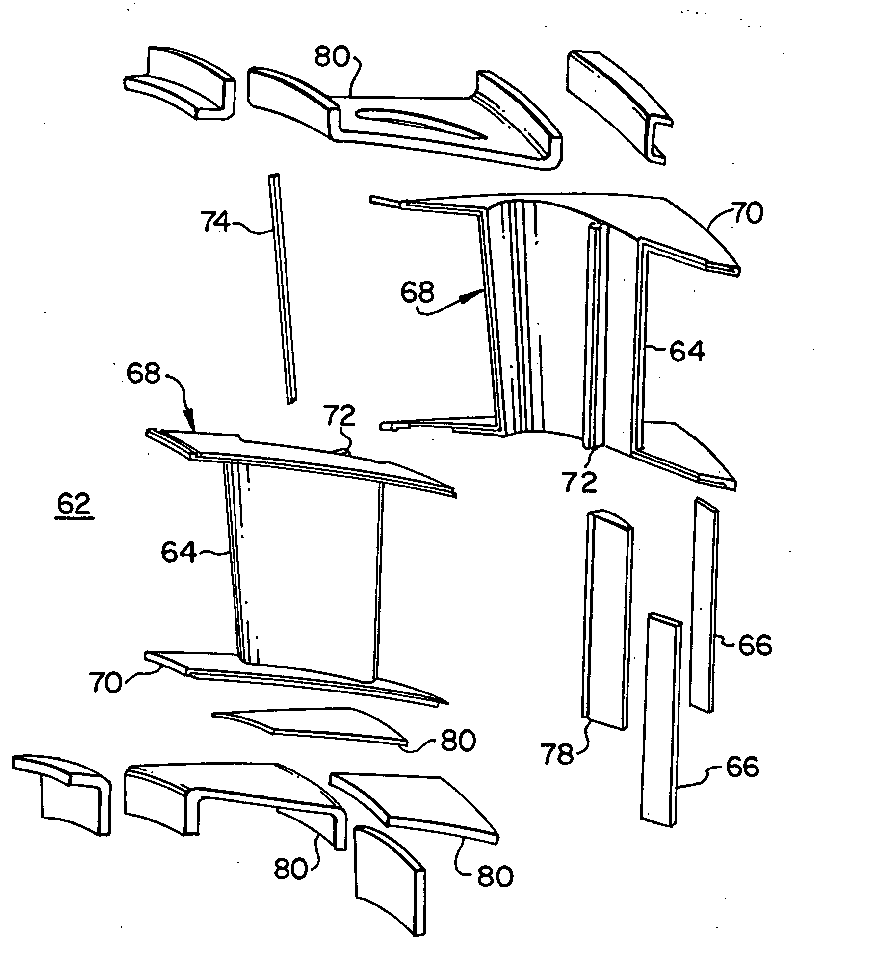
Composite structure formed by CMC-on-insulation process
a technology of ceramic matrix composites and composite structures, applied in the direction of manufacturing tools, machines/engines, stators, etc., can solve the problems of complicated bonding process, and achieve the effect of improving the ceramic composite structure and the manufacturing method
- Summary
- Abstract
- Description
- Claims
- Application Information
AI Technical Summary
Benefits of technology
Problems solved by technology
Method used
Image

Examples
Embodiment Construction
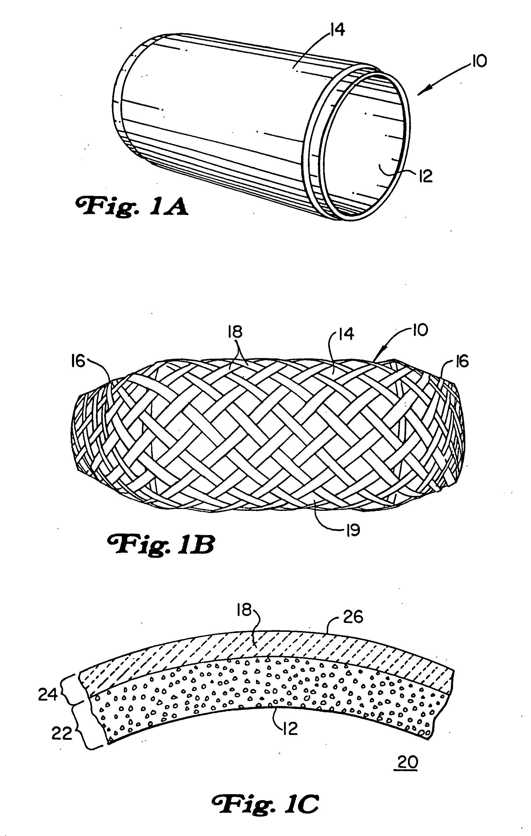
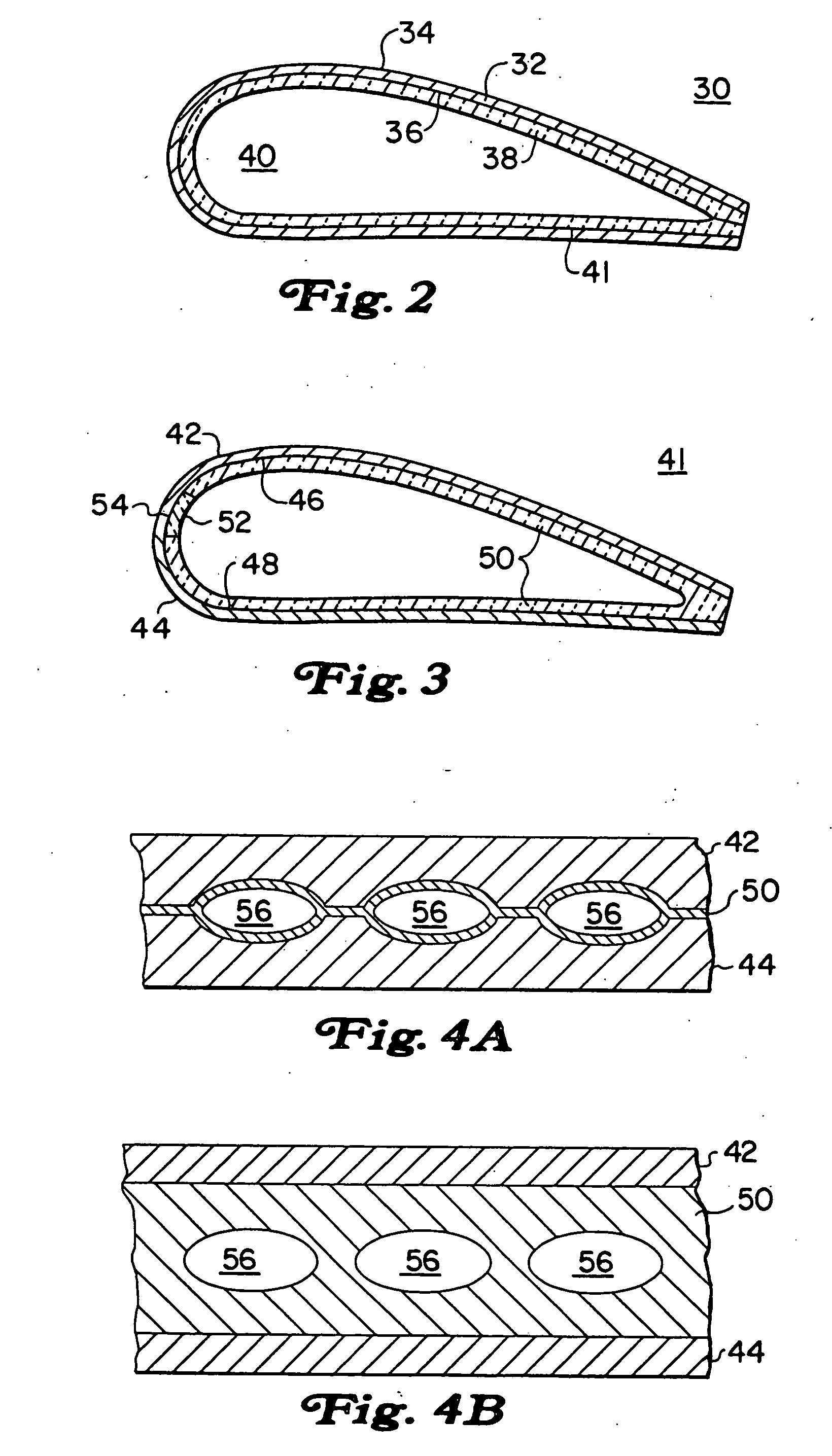
[0017] The applicants have found that an improved manufacturing process for ceramic composite structures is achieved by first forming a layer of thermally insulating material and then using the insulating layer as part of a mold for forming the CMC substrate layer. This process is broadly referred to as CMC-on-insulation, although the process is not limited to geometries where the CMC is physically on top of or above the insulating layer. The insulating layer is pre-formed using any known method to have a mating surface upon which the CMC layer is formed and / or shaped using any known method. The insulating layer mating surface may be cast or machined to a desired shape for receiving the CMC layer either with or without an intermediate layer or bonding agent. Using the insulation material as at least a portion of the mold for forming the CMC layer can simplify the tooling requirements for the CMC layer and it eliminates the problem of tolerances of mating surfaces between the CMC and...
PUM
| Property | Measurement | Unit |
|---|---|---|
| temperature | aaaaa | aaaaa |
| thermally insulating | aaaaa | aaaaa |
| structure | aaaaa | aaaaa |
Abstract
Description
Claims
Application Information