Hand-held compass saw

a compass saw and hand-held technology, applied in the direction of turning tools, metal sawing tools, sawing equipment, etc., can solve the problem of unclean saw cutting,

Inactive Publication Date: 2005-04-14
SCINTILLA AKTIENGES
View PDF1 Cites 3 Cited by
  • Summary
  • Abstract
  • Description
  • Claims
  • Application Information

AI Technical Summary

Problems solved by technology

With particularly narrow compass saw blades, there is a danger, however, that they are unable to be supported on both sides simultan

Method used


Image

  • Hand-held compass saw
  • Hand-held compass saw
  • Hand-held compass saw

Examples


Embodiment Construction

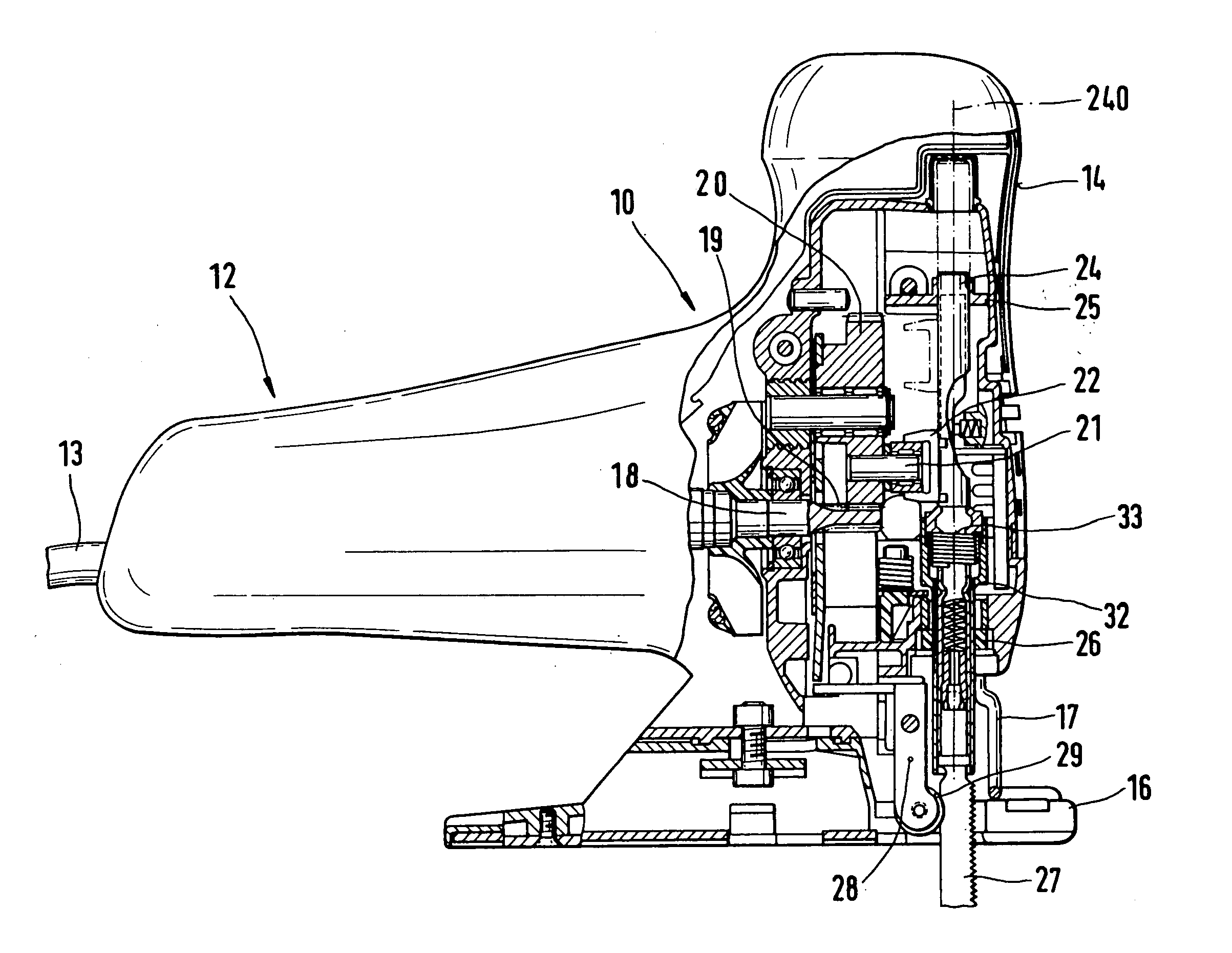
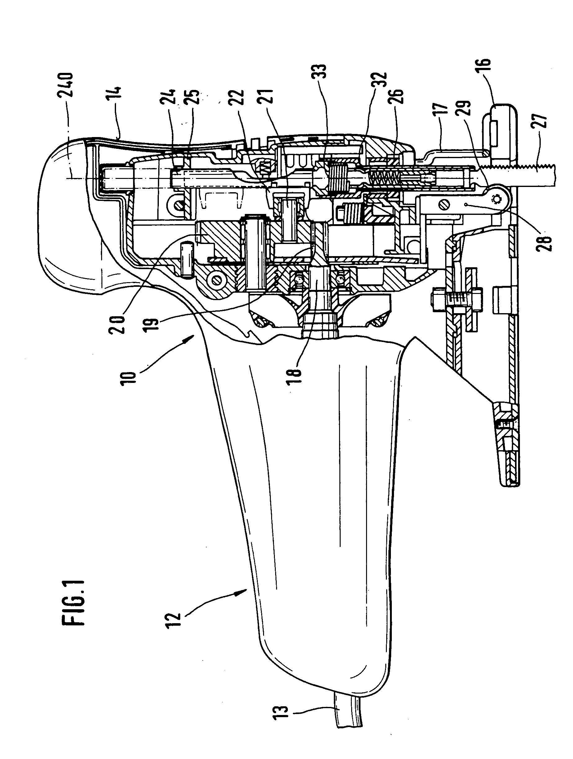
[0020] A compass saw 10 with a motor housing 12 serving as handle is shown in FIG. 1, the motor housing extending parallel with the feed direction and out of the back region of which an electrical cable 13 extends.

[0021] In the front region, compass saw 10 includes a gearbox case 14 that is flange-mounted to motor housing 12, the gearbox case, together with motor housing 12, being diametrically opposed—in a manner that allows the angle to be adjusted—to a base plate 16 for making mitre cuts. A rod-like mechanism for providing protection against accidental contact 17 is rigidly situated between gearbox case 14 and base plate 16 on gearbox case 14, the mechanism preventing accidental contact with a saw blade 27 from the front in the area of its saw teeth.

[0022] A motor, which is not shown in greater detail, imparts a rotary movement to its motor shaft 18, which ends in a shaft pinion 19 and extends into gearbox case 14. A gear wheel 20 meshes with shaft pinion 19, the gear wheel bei...


PUM

PropertyMeasurementUnit
Lengthaaaaaaaaaa
Angleaaaaaaaaaa
Angleaaaaaaaaaa

Abstract

A power compass saw (10) with a housing (12) that accommodates a lifting rod for the up and down movement of a longitudinal saw blade (27) attached thereto, the saw blade having a toothed side and a saw blade back (270), and with a guide roller (29) which supports the saw blade back (270) and has a central circumferential groove (290) into which the saw blade extends with its saw blade back (270) and is guided therein, whereby the sides of the circumferential groove (290) are tapered, the power compass saw functioning particularly precisely and efficiently due to the fact that the saw blade back (270) of the saw blade (27) is designed with a 7° conical configuration and/or taper on both sides, so that it tapers toward the saw blade back (270) and is capable of being supported in two dimensions in the circumferential groove (290), the groove sides (291) of which have a 5° taper.

Description

BACKGROUND INFORMATION [0001] The present invention is directed to a power compass saw having the features of the definition of the species in Claim 1. [0002] A power compass saw is known from GB patent 23 223 28, the reciprocating roller of which has a conical, central circumferential groove in which the saw blade back of a saw blade moved up and down in the power compass saw is to be supported. [0003] Compass saw blades are also known, the side surfaces of which are tapered toward the saw blade back at an acute angle, so that they are guided—laterally in two dimensions—in the reciprocating roller of the aforementioned power compass saw and are therefore relatively well supported. [0004] With particularly narrow compass saw blades, there is a danger, however, that they are unable to be supported on both sides simultaneously in the groove—which is too wide—of the reciprocating roller, thereby resulting in the danger that the saw cut will be unclean. ADVANTAGES OF THE INVENTION [0005...

Claims


Application Information

Patent Timeline
IPC IPC(8): B23D49/16B23D51/02B23D61/12B27B19/09
CPCB23D51/025B23D61/128B23D61/123
Inventor DELFINI, STEFANOKAISER, HANSSTOSS, PAULRUEPP, URS
Owner SCINTILLA AKTIENGES
Why Eureka
Try Eureka