Heat exchanger for fermentation tank

a technology of heat exchanger and fermentation tank, which is applied in the direction of biochemistry apparatus and processes, stationary tubular conduit assemblies, stationary conduit assemblies, etc., can solve the problems of uniform temperature control, unfavorable quality of beer produced, and formation of undesired sub-products

Inactive Publication Date: 2005-04-14
MORALES CERVANTES JOSE +1
View PDF2 Cites 46 Cited by
  • Summary
  • Abstract
  • Description
  • Claims
  • Application Information

AI Technical Summary

Benefits of technology

[0011] It is a purpose of this invention to have an internal vertical cooling equipment for fermentation tanks, which can use any kind of coolant inside beer fermentation, cooling and maturing tanks. System optimizes temperature control and distribution inside the tank during fermentation, resulting in a better quality beer, in addition to significantly shortening cooling time as compared to conventional systems.
[0031] This invention, consisting of a heat exchanger located internally, vertically positioned, corrects and upgrades traditional systems performance.

Problems solved by technology

In traditional design fermentation tanks, as capacity is increased, so increases their diameter, therefore when jackets are installed outside, cooling zone distance to center of the fermenter is increased reaching distances higher than five meters, causing temperature control not being uniform and inadequate liquid movement, thus promoting layers formation and temperature differences which sometimes are higher than 3° C., preventing a controlled fermentation, causing undesired sub-products formation.
This is quality detrimental for beer produced.
This forces some beer producers to limit fermentation tanks size in order to decrease such effect, which involves increasing investment costs, as more fermentation tanks have to be acquired and consequently increasing beer production costs.
Likewise, using external cooling jackets limits tank geometry design, since in order to account for a higher heat transmission area from external cooling jackets and higher cooling speed, a straight section height / tank diameter high ratio, higher than 2:1 is required, which is against technological requirements for quality beer production.

Method used


Image

  • Heat exchanger for fermentation tank
  • Heat exchanger for fermentation tank
  • Heat exchanger for fermentation tank

Examples


Embodiment Construction

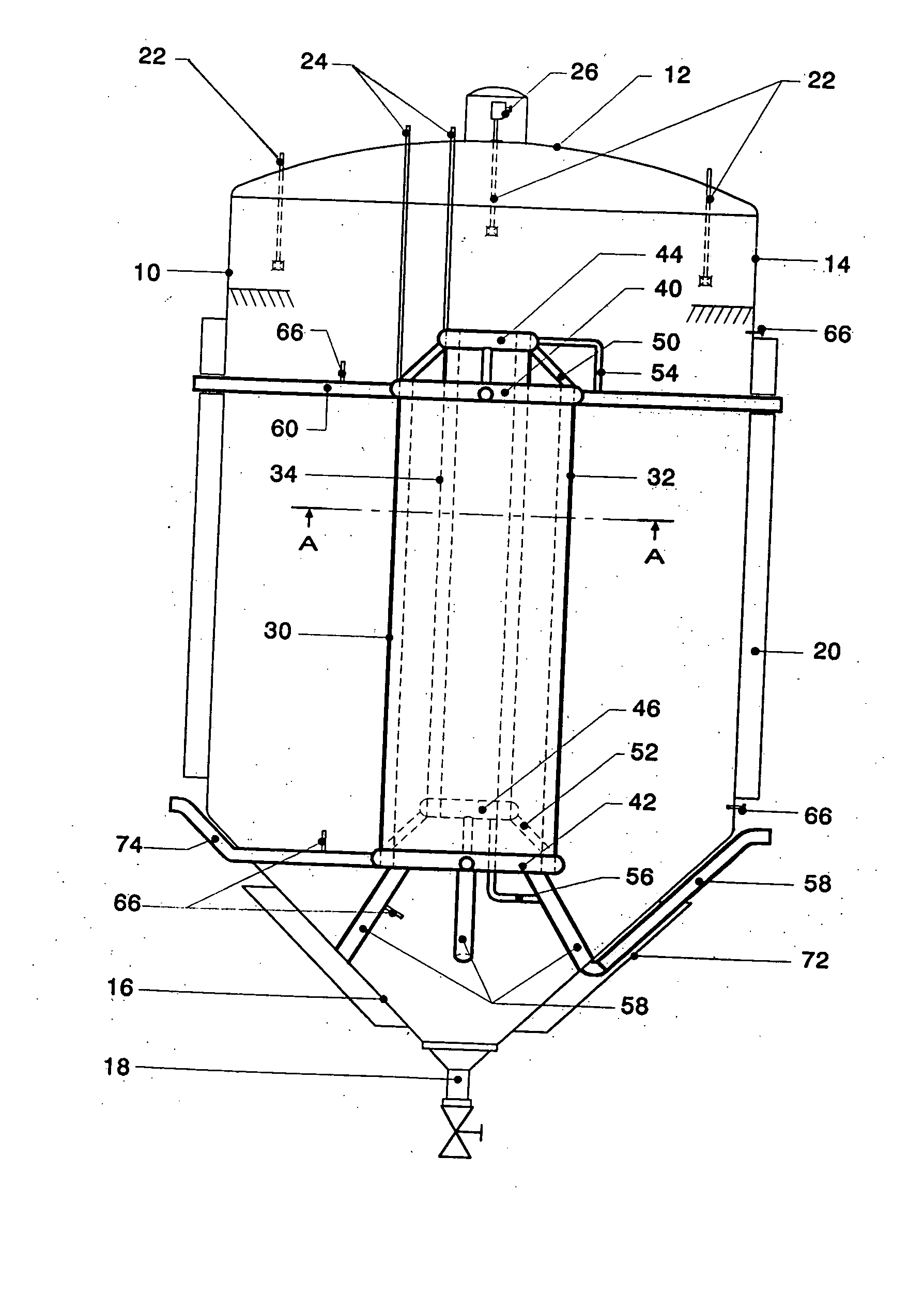
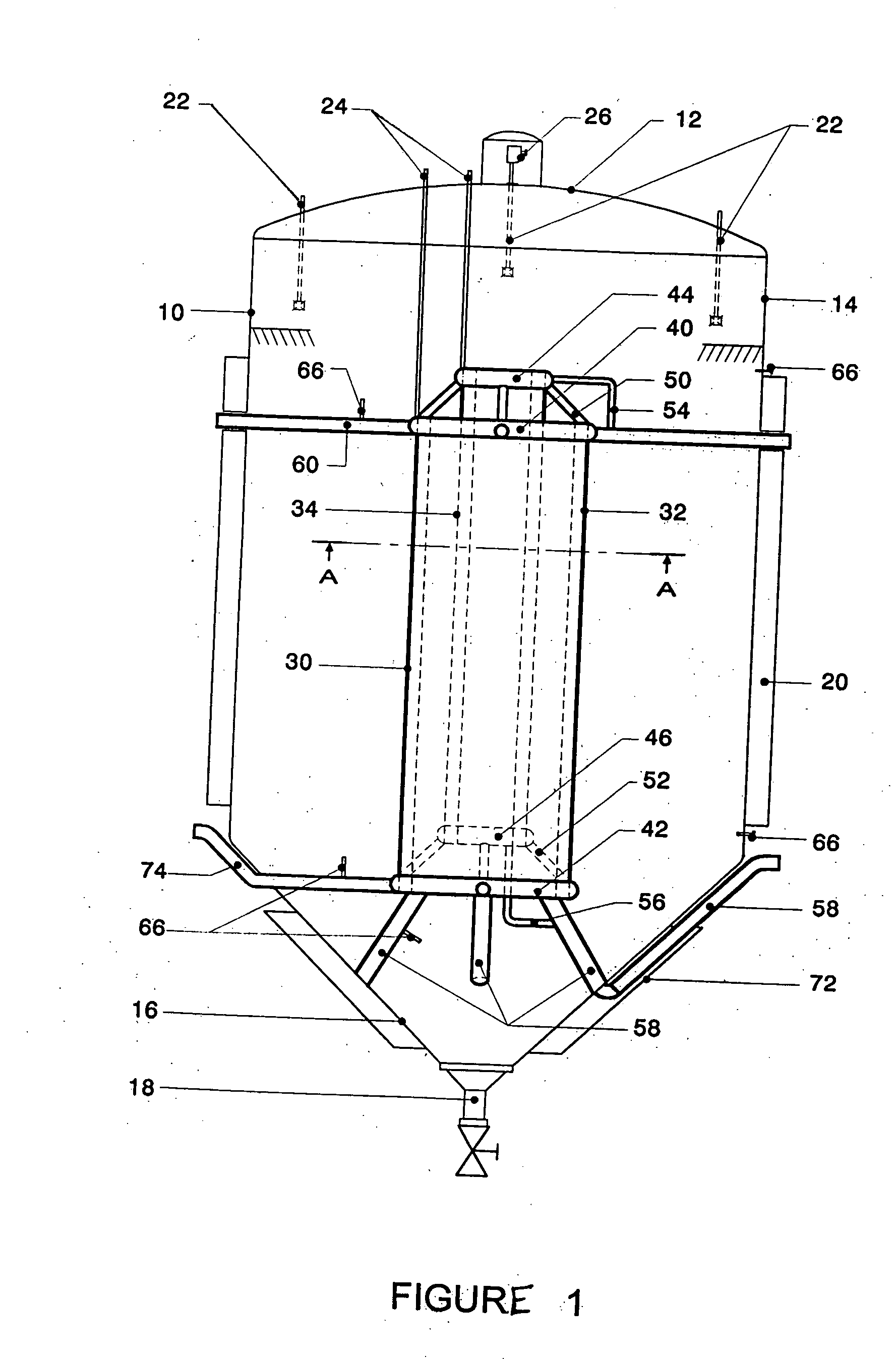
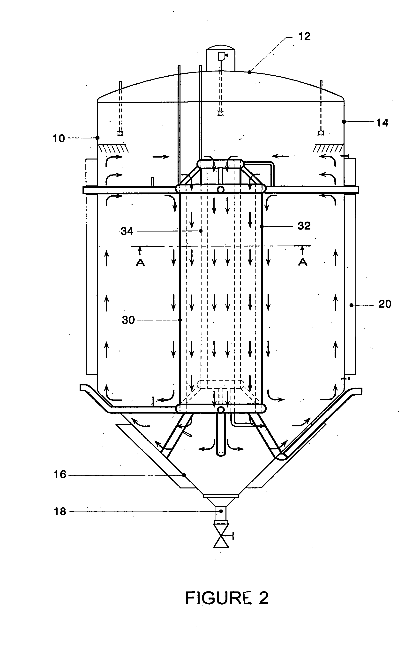
[0041] As referring to said figures and following same nomenclature of reference signs shown, this invention consists of an internal vertical heat exchanger 30, to be installed inside a tank 10, three main sections are underlined from the latter: an upper, dome cap 12, whose function will be to maintain sufficient space as to store gases formed during fermentation process; a cylindrical body 14, whose function will be to contain beer wort to carry out fermentation process, whose exothermal reaction requires cooling and also to cool the beer after fermentation, to do so a cooling jacket 20 may be fitted on external wall, the whole fermentation tank is usually isolated in order to decrease heat losses toward environment and, the conic-shaped bottom 16, with variable design angle, whose function will be to receive and store deposited particles, which are finally extracted by a lower valve 18, same as wort and beer after separating deposits.

[0042] Inside fermentation tank 10, a heat ex...


PUM

PropertyMeasurementUnit
temperatureaaaaaaaaaa
diameteraaaaaaaaaa
weightaaaaaaaaaa

Abstract

A device which is used to cool fermentation tanks and which can be used essentially in beer production, cooling and maturation, includes a vertical heat exchanger, which comprises single- or double-wall concentric cylinders and is positioned internally at the center of a tank. The length and capacity of the cylinders differ depending on the size and shape of the tank. A coolant flows through the cylinders in order to cool and to maintain a suitable temperature range. In addition, the double-wall cylinders which form the heat exchanger are interconnected by means of coolant flow and support tubes. Meanwhile, the exchanger is supported by the cone and the walls of the tank by means of tubes which are used for the passage of the coolant and the passage of signals. Moreover, the outer wall and the cone can be provided with a cooling jacket.

Description

RELATED U.S. APPLICATIONS [0001] Not applicable. STATEMENT REGARDING FEDERALLY SPONSORED RESEARCH OR DEVELOPMENT [0002] Not applicable. REFERENCE TO MICROFICHE APPENDIX [0003] Not applicable. FIELD OF THE INVENTION [0004] An accessory for cooling fermentation tanks is presented, which can be primarily used in beer production, cooling and maturing, however, it can also be used in wine production and fermentation, in fermentable alcoholic beverages or milk production and dairy products. BACKGROUND OF THE INVENTION [0005] Upgraded fermentation equipment is composed by a combination of a heat exchanger internally located, vertically positioned, inside a tank, which includes some double-wall concentric cylinders, whose length and capacity may feature different dimensions, depending on tank size and geometry, and through said heat exchanger a coolant will pass to cool liquid to adequate temperature for processes, coolant is supplied and recovered by distributors which may be set in upper ...

Claims


Application Information

Patent Timeline
Patent Type & Authority Applications(United States)
IPC IPC(8): C12C11/00C12G1/028F28D1/02F28D7/10F28D11/02
CPCC12G1/0213F28D7/106F28D7/103F28D1/0213
Inventor MORALES CERVANTES, JOSESOTO-PORRUA, ANGEL JOSE ENRIQUE
Owner MORALES CERVANTES JOSE
Why Eureka
Try Eureka