Inline compensator for a floating drill rig

Inactive Publication Date: 2005-04-14
NAT OILWELL DHT
View PDF30 Cites 86 Cited by
  • Summary
  • Abstract
  • Description
  • Claims
  • Application Information

AI Technical Summary

Benefits of technology

[0010] An apparatus for providing a back-up heave compensation system is disclosed. The disclosed invention is a unique inline compensator in which a plurality of cylinders housed within a tubular housing and one or more low pressure and high pressure accumulators function together to provide a system for compensating for heave in the event a primary heave compensation system fails or becomes inoperative. The inline compensator of

Problems solved by technology

The movement of drill ships or semi-submersible drilling rigs with the waves of the sea presents a unique problem in drilling with these types of rigs.
This fluctuation in the force applied on the drill bit severely hinders an operator's ability to drill the well bore.
Perhaps more importantly, heave creates the potential for blowouts due to a potential fracturing or breaking of the production tubing during testing, workover, or completion operations.
Because the production tubing is held in place within the well bore, any rise of the floating drilling rig due to heave will increase the tension on the production tubing string and could cause the string to fracture or break.
A fracturing or breaking of the production tubing string would allow the oil or gas within the tubing to leak, creating the potential for a blowout.
However, prior art floating drilling rigs are generally not

Method used


Image

  • Inline compensator for a floating drill rig
  • Inline compensator for a floating drill rig
  • Inline compensator for a floating drill rig

Examples


Embodiment Construction

[0032] The following examples are included to demonstrate preferred embodiments of the invention. It should be appreciated by those of skill in the art that the techniques disclosed in the examples which follow represent techniques discovered by the inventors to function well in the practice of the invention, and thus can be considered to constitute preferred modes for its practice. However, those of skill in the art should, in light of the present disclosure, appreciate that many changes can be made in the specific embodiments which are disclosed and still obtain a like or similar result without departing from the spirit and scope of the invention.

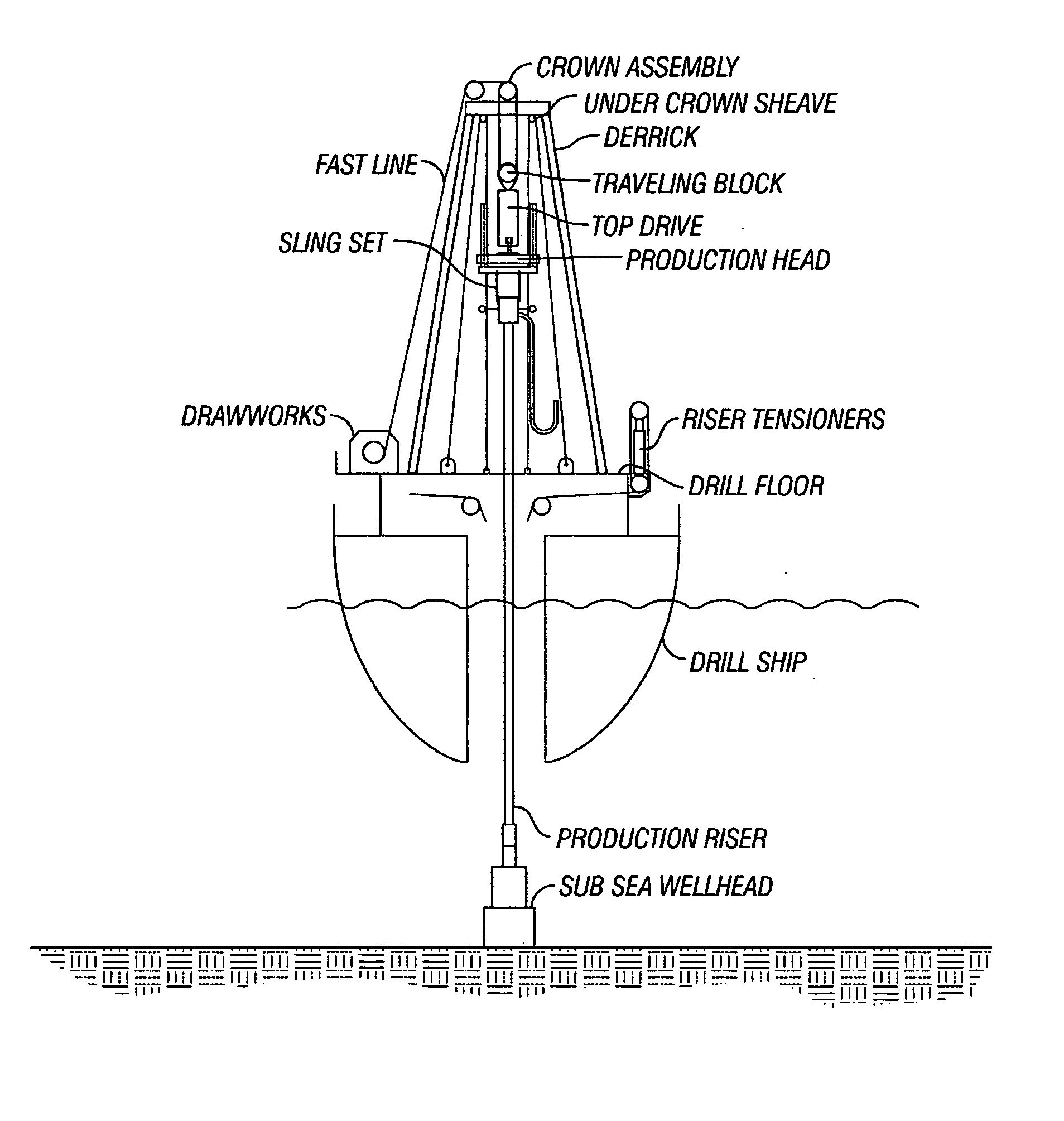
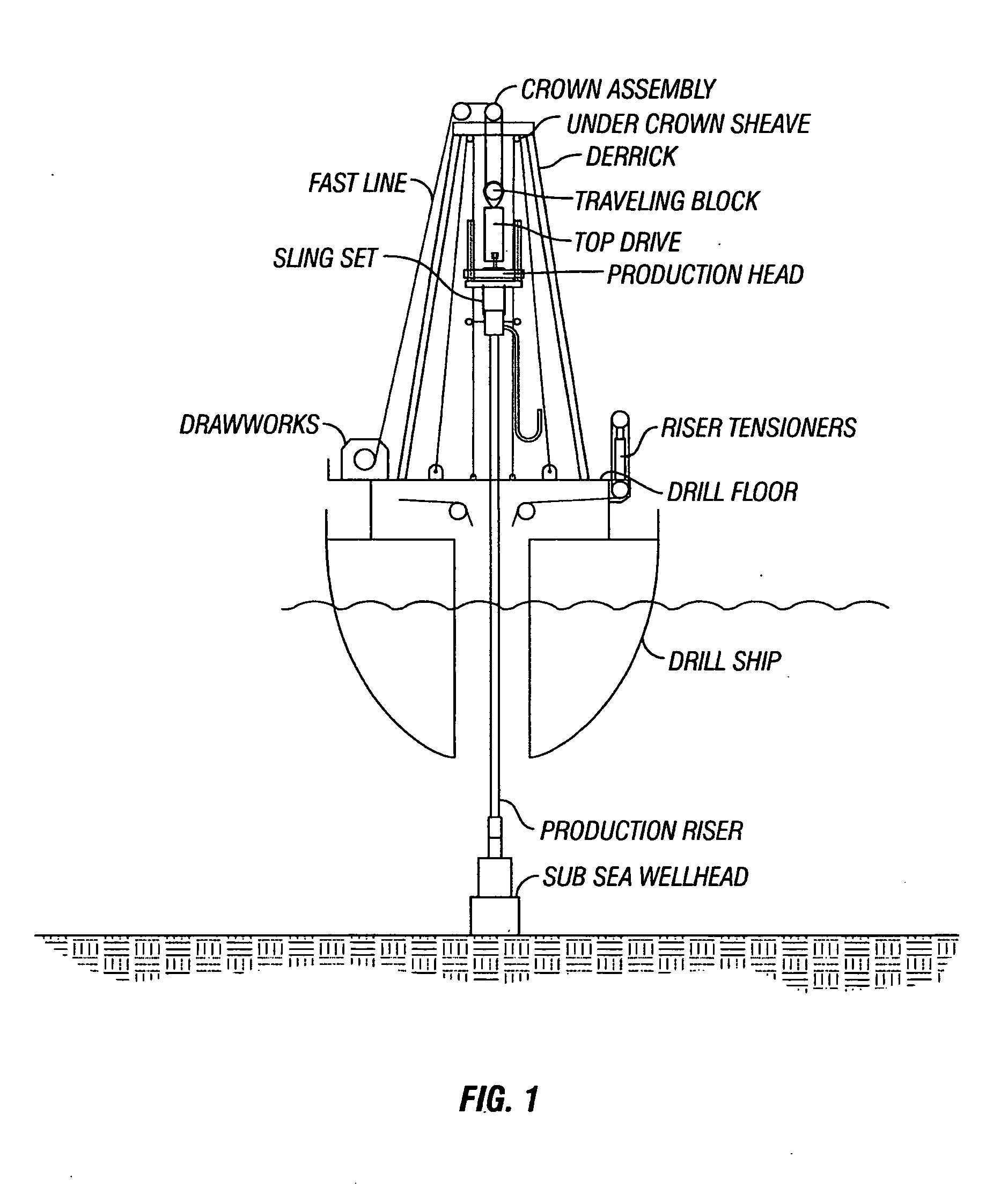
[0033] Referring to FIG. 1, various components of a typical drill ship are shown. As shown in FIG. 1, the drill ship has a drill floor that supports a riser tensioning system that maintains the production riser (the conduit that extends from the drill ship to the subsea Christmas tree or wellhead) in tension. The drawworks for the rig is...


PUM


Abstract

An apparatus and method for protecting against the problems associated with heave of a floating drilling rig are disclosed. The disclosed invention is a unique inline compensator in which a plurality of cylinders housed within a tubular housing and a plurality of low pressure and high pressure accumulators function together to provide a system for compensating for heave in the event a primary heave compensation system fails or becomes inoperative. The typical inline compensator of the present invention utilizes a plurality of hydraulic cylinders that act in opposite directions and that have different piston areas such that the piston rods of the cylinders are extended or retracted at different pressure levels to account for heave. The typical inline compensator of the present invention is self-contained and compact enough to fit in the limited space available on a floating drilling structure. Further, a pair of inline compensators of the present invention can be utilized with coiled tubing operations. In such a case, the inline compensators will not interfere with the tooling necessary to conduct the coiled tubing operations.

Description

[0001] This application claims the benefit of U.S. Provisional Application No. 60 / 509,623, filed Oct. 8, 2003.FIELD OF THE INVENTION [0002] The present invention relates to an inline compensator apparatus and method for use on floating drilling rigs and workover or production vessels. In particular, the invention relates to an inline compensator apparatus that functions as a back-up system for the primary or main heave compensation system of a floating drilling rig or vessel in the event the primary heave compensation system becomes disabled or inoperative. BACKGROUND OF THE INVENTION [0003] Drilling for oil and gas off-shore is completed from one of two types of drilling rigs: rigs that are supported by the sea floor (such as fixed drilling rigs or jack-up drilling rigs) or rigs that float on the surface of the water (such as drill ships or semi-submersible drilling rigs). Although drilling operations conducted from these two types of drilling rigs are similar, at least one major d...

Claims


Application Information

Patent Timeline
IPC IPC(8): E21B19/09
CPCE21B19/09E21B19/006
Inventor MOE, MAGNE MATHIASKYLLINGSTAD, AGE
Owner NAT OILWELL DHT
Why Eureka
Try Eureka