Method and apparatus for localized control of a plasma cutter

a plasma cutter and local control technology, applied in plasma welding apparatus, plasma technique, manufacturing tools, etc., can solve the problems of system numerous drawbacks, limited number of sensors to provide feedback, and limited number of communications links, so as to reduce intercomponent dependencies, reduce communication links throughout the plasma cutting system, and increase the response time to feedback

Inactive Publication Date: 2005-04-14
ILLINOIS TOOL WORKS INC
View PDF12 Cites 24 Cited by
  • Summary
  • Abstract
  • Description
  • Claims
  • Application Information

AI Technical Summary

Benefits of technology

[0009] The present invention is directed to a system and method of coordinating operational feedback in a plasma cutter that overcomes the aforementioned drawbacks. Specifically, the present invention provides a system and method to localize feedback and control of a plasma cutting system such that communication links throughout the plasma cutting system are reduced, response time to feedback is increased, and intercomponent dependencies are reduced.

Problems solved by technology

However, this system presents numerous drawbacks.
However, while it is common to provide a cup-attached signal before permitting operational cutting, additional feedback is limited by the number of communication links between the feedback system located in the torch and the processing unit located in the power source.
As such, though additional sensors could be included to provide additional feedback regarding the plasma cutting process, the number of sensors to provide feedback is limited by the number of communications links.
Second, such systems are dependent upon the power source for operational control.
Therefore, incremental upgrades are generally cost prohibitive.

Method used


Image

  • Method and apparatus for localized control of a plasma cutter
  • Method and apparatus for localized control of a plasma cutter
  • Method and apparatus for localized control of a plasma cutter

Examples


Embodiment Construction

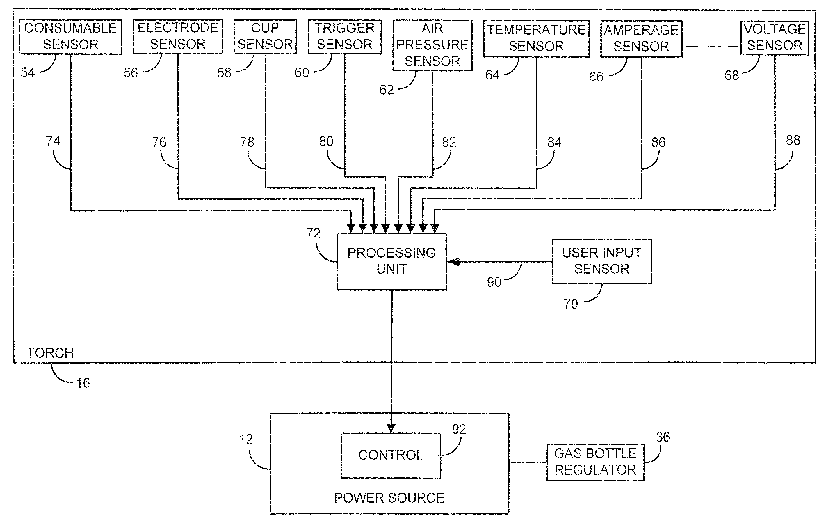
[0019] The present invention is directed to an localized control system for a plasma cutter. Specifically, the present invention provides a system and method of to localize a feedback and control system of a plasma cutting system such that communication links throughout the plasma cutting system are reduced, response time to feedback is increased, and inter-component dependencies are reduced.

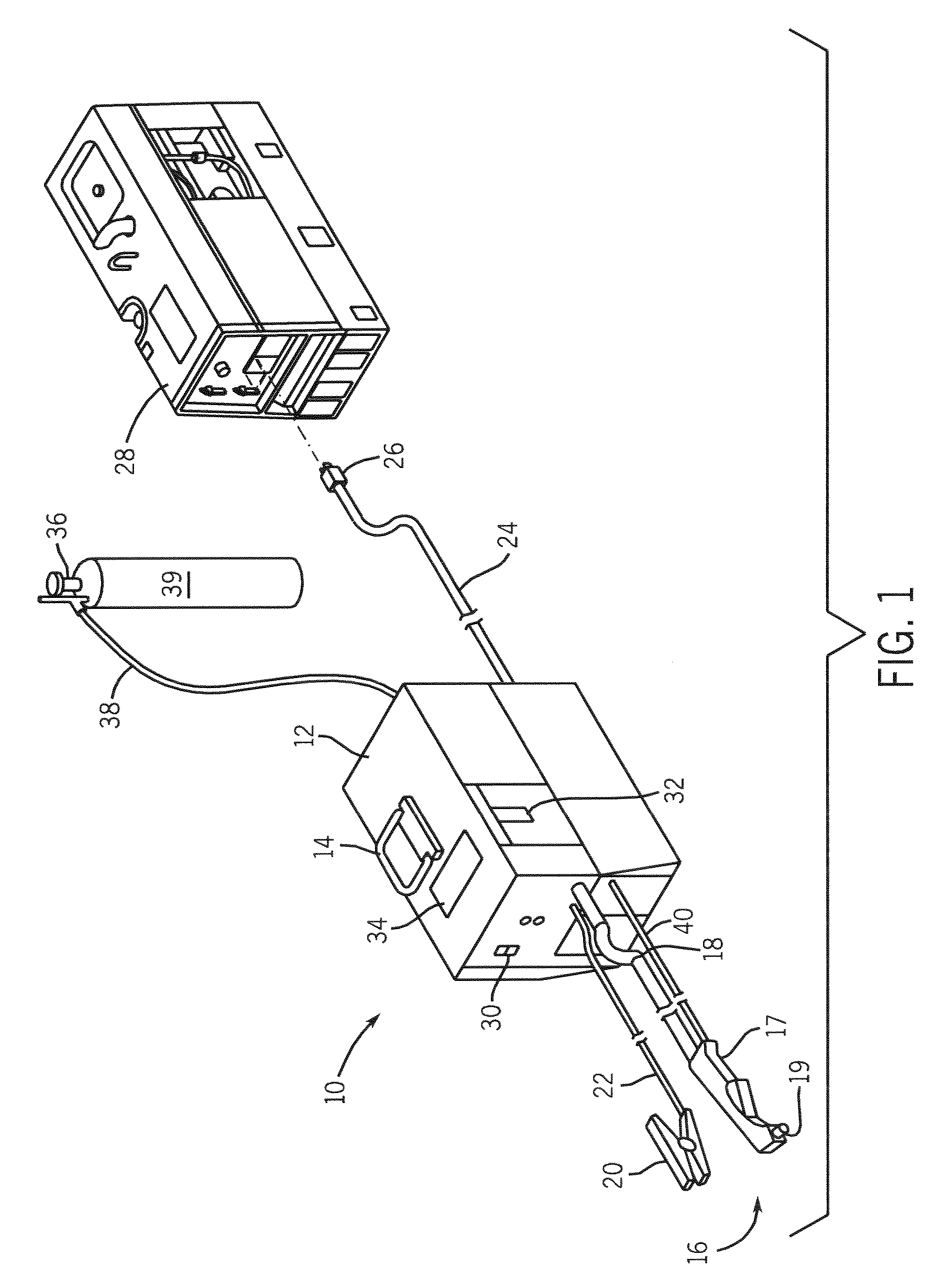
[0020] Referring to FIG. 1, a plasma cutting system 10 is shown. The plasma cutting system is a high voltage system with maximum open circuit output voltages ranging from approximately 230 Volts Direct Current (VDC) to over 300 VDC. The plasma cutting system 10 includes a power source 12 to condition raw power and regulate / control the cutting process. Specifically, the power source includes a processor that, as will be described, receives operational feedback and controls the plasma cutting system 10 accordingly. Power source 12 includes a lifting means handle 14 which effectuates transportatio...


PUM

PropertyMeasurementUnit
open circuit output voltageaaaaaaaaaa
voltagesaaaaaaaaaa
plasma cutting poweraaaaaaaaaa

Abstract

The present invention is directed to a system and method for a plasma cutting system including a plasma cutting power source and a plasma torch operationally connected to the plasma cutting power source. A processing unit is disposed within the plasma torch and is configured to control the plasma cutting power source during a plasma cutting process based on operational feedback gathered of the plasma cutting process.

Description

BACKGROUND OF INVENTION [0001] The present invention relates generally to plasma cutting systems and, more particularly, to a method and apparatus for localized feedback and control systems. Specifically, the present invention provides a system and method of controlling a plasma cutting process by localizing feedback sensors and a processing unit within a plasma-cutting torch. [0002] Plasma cutting is a process in which an electric arc is used to cut a workpiece. Plasma cutters typically include a power source, an air supply, and a torch. The torch or plasma torch is used to create and maintain the arc and plasma that perform the cutting. The plasma cutting power source receives an input voltage from a transmission power line or generator and provides an output voltage to a pair of output terminals, one of which is connected to an electrode and the other of which is connected to the workpiece. [0003] The air supply is used with most plasma cutters to help start the arc, provide the ...

Claims


Application Information

Patent Timeline
Patent Type & Authority Applications(United States)
IPC IPC(8): B23K10/00H05H1/34H05H1/36
CPCB23K10/006H05H2001/3494H05H1/36H05H1/3494
Inventor MATUS, TIM A.LAMBERT, DAVIDSCHNEIDER, JOSEPH C.ULRICH, JAMES F.
Owner ILLINOIS TOOL WORKS INC
Why Eureka
Try Eureka