Electro-optical device and electronic apparatus

a technology of optical devices and electronic equipment, applied in the field of optical devices, can solve the problems of picture quality degradation, related techniques of providing a dummy area as described, and achieve the effect of improving the picture quality in the proximity of the edges of an image displayed, and stable potential

Active Publication Date: 2005-04-14
138 EAST LCD ADVANCEMENTS LTD
View PDF1 Cites 61 Cited by
  • Summary
  • Abstract
  • Description
  • Claims
  • Application Information

AI Technical Summary

Benefits of technology

[0033] In another mode of the electro-optical device according to the present invention, the dummy-pixel light-shielding film can be connected to a constant potential source or a constant potential wire. According to this mode, the potential of the dummy-pixel light-shielding film is stable, so that variation of the potential does not substantially cause negative effect on pixel electrodes, wires, or other parts. Preferably, the constant potential wire is a ground potential wire of the data-line driving circuit, which is usually connected relatively close to the dummy pixel electrodes considering the layout on the substrate. Alternatively, a dedicated constant potential source or constant potential wire may be provided.
[0034] In another mode of the electro-optical device according to the invention, the dummy-pixel light-shielding film is at a floating potential. This mode is convenient when the dummy-pixel light-shielding film is formed as island-shaped segments. As long as the dummy-pixel light-shielding film is at an interlayer distance from other conductive layers or semiconductor layers, the dummy-pixel light-shielding film, even if it is at a floating potential, does not negatively affect other parts. Furthermore, when the capacitance of the dummy-pixel light-shielding film is large, even if the dummy-pixel light-shielding film is at a floating potential, it is possible to maintain a stable potential. Thus, the dummy-pixel light-shielding film may be at a floating potential when, for example, the...

Problems solved by technology

However, the related techniques of providing a dummy area as described above suffer the following problems.
This results in a technical problem that picture quality is degraded, particularly in the proximi...

Method used


Image

  • Electro-optical device and electronic apparatus
  • Electro-optical device and electronic apparatus
  • Electro-optical device and electronic apparatus

Examples


third embodiment

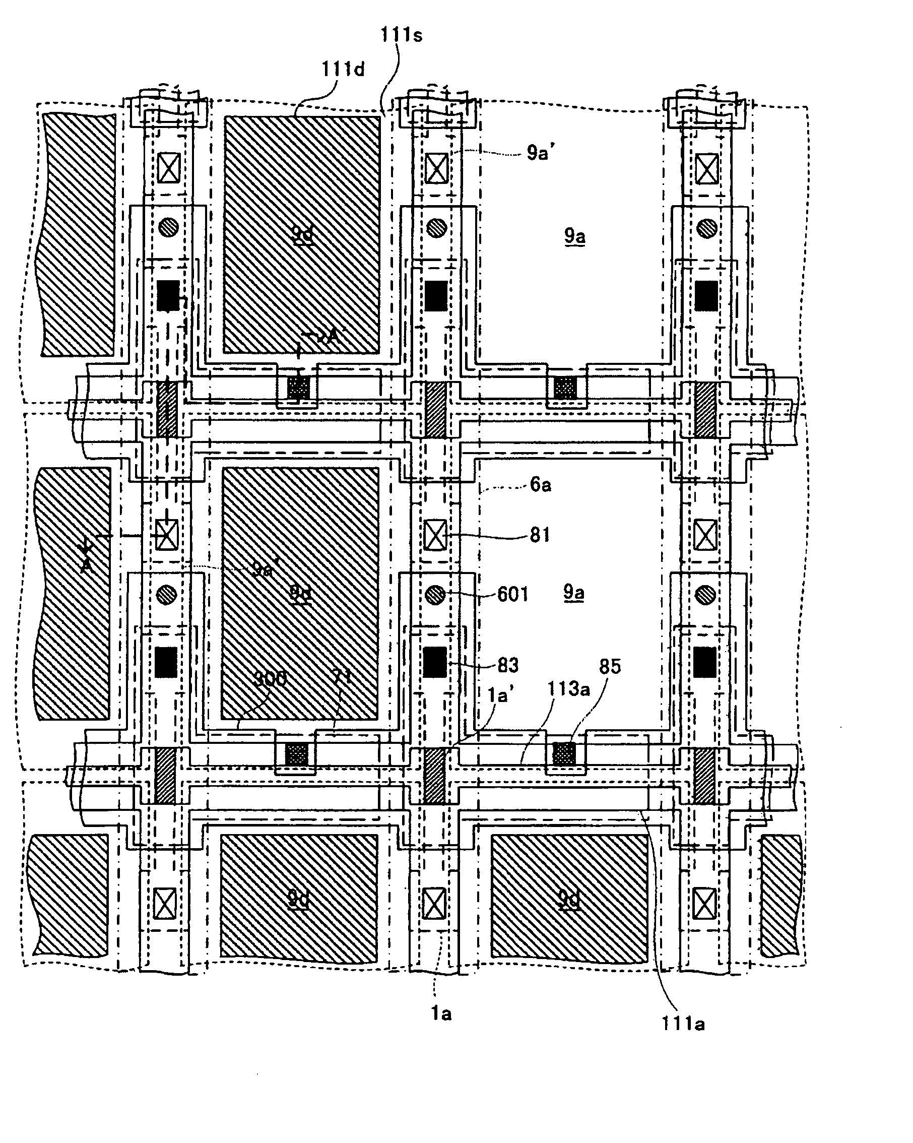
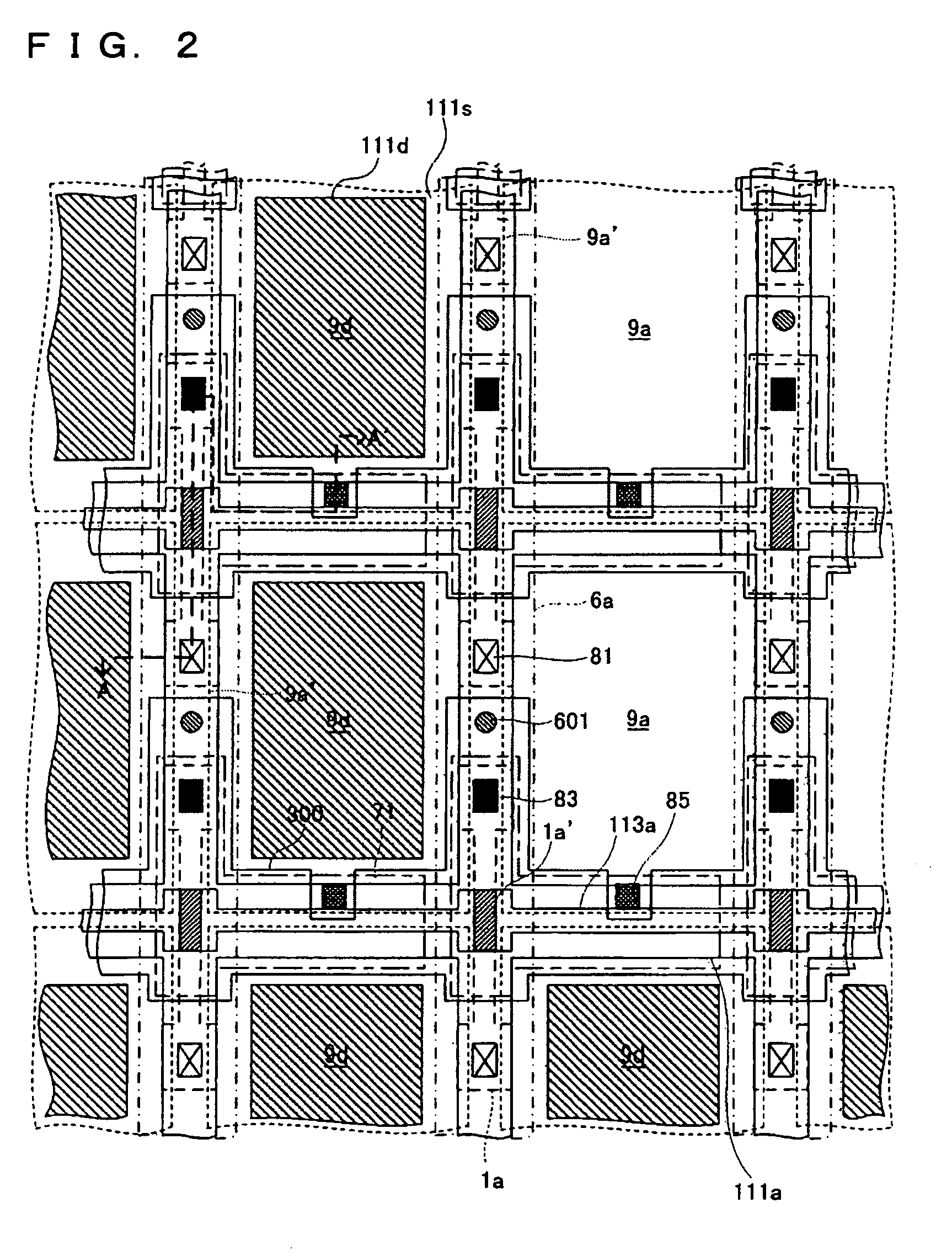
[0105] Next, a third exemplary embodiment of the invention will be described with reference to FIGS. 8 to 11. FIGS. 8 and 9 are plan views of a plurality of adjacent pixels on a TFT array substrate where data lines, scanning lines, pixels electrodes, and other associated parts are formed. FIGS. 8 and 9 are plan views showing parts corresponding to those shown in FIG. 2. FIGS. 8 and 9 respectively show lower layers and upper layers of a multilayer structure described later. FIG. 10 is a sectional view of the multilayer structure shown in FIGS. 8 and 9, taken along a line A-A′. In FIG. 10, layers and parts are shown in different scales so as to allow recognition of the layers and the parts in the figure. FIG. 11 is a plan view showing a planar pattern of lower light-shielding films in a dummy area in the

[0106] In FIGS. 8 to 11 relating to the third embodiment, parts corresponding to those shown in FIGS. 1 to 6 in relation to the first embodiment are designated by the same numerals, an...

second embodiment

[0123] According to the third exemplary embodiment, the opening regions of the dummy pixels are covered by the dummy-pixel light-shielding films 111d-3 formed as island-like segments. Thus, stress that occurs in the proximity of the dummy-pixel light-shielding films 111d-3 due to a thermal history during manufacturing processes is alleviated, and this serves to prevent occurrence of cracks. Furthermore, since the island-shaped lower light-shielding films 111d-3 similar to the opening regions are formed even though gaps 111s having a width on the order of several μm are provided along the edges of the opening regions, light is blocked substantially the same as in the second embodiment where the opening regions are entirely covered. That is, the dummy-pixel light-shielding films 111d-3 sufficiently block light in the dummy area.

[0124] Furthermore, since the dummy-pixel light-shielding films 111d-3 are island shaped, it is possible to insulate the individual dummy-pixel light-shielding...

fifth embodiment

[0130] Next, a fifth exemplary embodiment of the present invention will be described with reference to FIG. 13. FIG. 13 is a plan view showing a planar pattern of a dummy-pixel light-shielding film in a dummy area in the

[0131] Referring to FIG. 13, in an electro-optical device according to the fifth embodiment, a dummy-pixel light-shielding film 111d-5 have slits 111s1-1 that are horseshoe-shaped as viewed in plan.

[0132] According to this embodiment, since the dummy-pixel light-shielding film 111d-5 has the slits 111s1-1, stress that occurs in the proximity of the dummy-pixel light-shielding film 111d-5 due to a thermal history during manufacturing processes is alleviated, and this serves to prevent occurrence of cracks. Furthermore, since the widths of the slits 111s1-1 are as small as on the order of several μm, the dummy-pixel light-shielding film 111d-5 sufficiently blocks light.

[0133] The electrical connection over the entire dummy-pixel light-shielding film 111d-5 is not bro...


PUM


Abstract

Aspects of the invention can provide an electro-optical device that displays an image in good quality by an electro-optical device, such as a liquid crystal device, even in the proximity of edges of the image displayed. The electro-optical device can include a plurality of pixel electrodes, and wires and electronic elements that are used to drive the pixel electrodes, provided on a substrate. The plurality of pixel electrodes can be arranged in an image display area and a dummy area. The pixel electrodes disposed in the dummy area function as dummy pixel electrodes. Furthermore, on the substrate, dummy-pixel light-shielding films that cover at least part of opening regions of the dummy pixel electrodes are provided.

Description

BACKGROUND OF THE INVENTION [0001] 1. Field of Invention [0002] Aspects of the invention relates to the technical field of electro-optical devices, such as liquid crystal devices, and electronic apparatuses, such as liquid crystal projectors including such electro-optical devices. [0003] 2. Description of Related Art [0004] Related electro-optical device of this type can include a plurality of pixel electrodes arranged in a matrix shape, for example, on a thin-film transistor (TFT) array substrate, and a planar area where the plurality of pixel electrodes is arranged is used as an image display area. The image display area can have a frame defined, for example, by an internal light-shielding film referred to as a black matrix or a black mask, formed on the TFT array substrate. Alternatively or in addition to the internal light-shielding film, a frame-shaped light-shielding film can be formed on an opposing substrate. [0005] However, of the plurality of pixel electrodes arranged in a...

Claims


Application Information

Patent Timeline
IPC IPC(8): G02F1/13G02F1/133G02F1/1333G02F1/1343G02F1/136G02F1/1362G02F1/1368G09F9/30H01L29/786
CPCG02F2001/133388G02F1/136209G02F1/133388G02F1/1343
Inventor MURADE, MASAO
Owner 138 EAST LCD ADVANCEMENTS LTD
Why Eureka
Try Eureka