Surface profiling using an interference pattern matching template

a surface profiling and pattern matching technology, applied in the field of interferometric analysis of objects, can solve problems such as erroneous spatial information regarding the substrate surface and film-air interfa

Inactive Publication Date: 2005-04-14
ZYGO CORPORATION +1
View PDF66 Cites 89 Cited by
  • Summary
  • Abstract
  • Description
  • Claims
  • Application Information

AI Technical Summary

Benefits of technology

One aspect of the invention relates to methods and systems for analyzing low coherence interference signals from objects producing interference patterns that overlap as a function of optical path length difference (OP

Problems solved by technology

Such overlapped interference patterns can provide erroneous spatial

Method used


Image

  • Surface profiling using an interference pattern matching template
  • Surface profiling using an interference pattern matching template
  • Surface profiling using an interference pattern matching template

Examples


examples

Determining a spatial property of a measurement object is further described the context of the following non-limiting examples.

1. Determining a Spatial Property of a Single-Surface Measurement Object

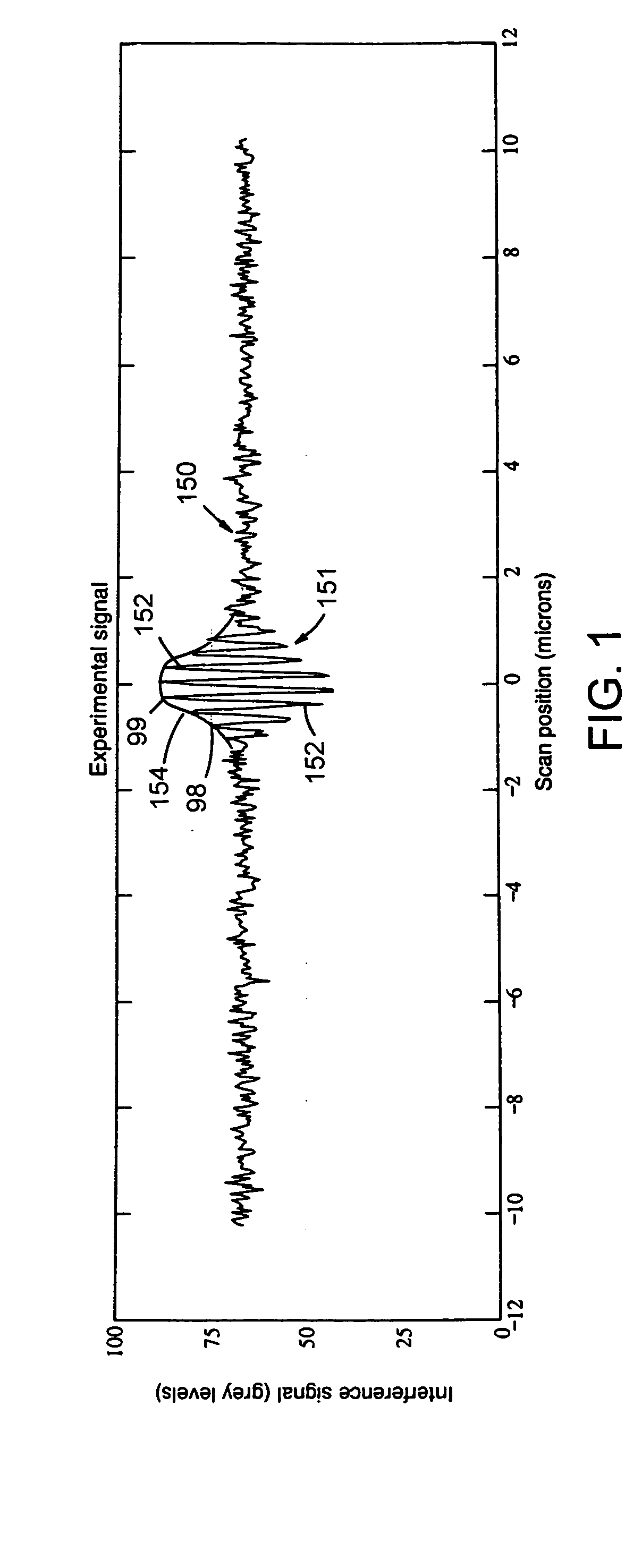
Referring to back to FIG. 1, interference signal 150 is but one of a total 101 interference signals representing a linear trace across the object surface. For convenience, the remaining 100 interference signals are not shown. The silicon dioxide object surface has an approximately spherical profile with PV=600 nm. The irradiation wavelength is 550 nm with a bandwidth of 100 nm. The bandwidth is Gaussian in wavenumber. The numerical aperture is 0.01 for normal incidence, collimated light. Each interference signal has a full scale digital resolution of 256 grey scale steps. The average signal strength is 20 grey levels amplitude AC above 65 grey levels DC. The signals have random noise having a standard deviation of 2 grey levels.

The 101 interference signals are transformed to an in...


PUM


Abstract

A method for determining a spatial property of an object includes obtaining a scanning low coherence interference signal from a measurement object that includes two or more interfaces. The scanning low coherence interference signal includes two or more overlapping low coherence interference signals, each of which results from a respective interface. Based on the low coherence interference signal, a spatial property of at least one of the interfaces is determined. In some cases, the determination is based on a subset of the low coherence interference signal rather than on the entirety of the signal. Alternatively, or in addition, the determination can be based on a template, which may be indicative of an instrument response of the interferometer used to obtain the low coherence interference signal.

Description

FIELD OF THE INVENTION The invention relates to interferometric analysis of objects, such as to interferometric determination of an object topography. BACKGROUND Interferometry may be used to determine a spatial property of an object. Typical spatial properties include a surface topography or location of the object with respect to some reference. For objects including a thick film overlying an opaque substrate the data may include two interference patterns resulting, respectively, from the substrate-film interface and film-air interface. If the interfaces are widely spaced, the data can sometimes provide independent information about the substrate surface and film-air interface. As the overlying film becomes thinner, the respective interference patterns begin to overlap and distort one another. Such overlapped interference patterns can provide erroneous spatial information regarding the substrate surface and film-air interface. SUMMARY One aspect of the invention relates to metho...

Claims


Application Information

Patent Timeline
IPC IPC(8): G01B9/02G01B11/00G01B11/06G03F7/20G03F9/00
CPCG01B11/0675G01B2290/30G03F7/70608G03F7/70641G03F7/70775G03F9/7003G03F9/7049G03F9/7088G01B9/02019G01B9/0209G01B9/02022G01B2290/70G01B9/02084G01B9/02087G03F7/70491G01B9/02G03F7/20G03F7/00
Inventor DE GROOT, PETER J.
Owner ZYGO CORPORATION
Why Eureka
Try Eureka