X-ray diagnosis apparatus

a diagnostic apparatus and x-ray technology, applied in the field of x-ray diagnosis apparatus, can solve the problems of difficult to acquire offset data in radiography mode, inability to secure the period of no, and image artifact generation, and achieve the effect of eliminating artifacts from radiographic images

Inactive Publication Date: 2005-04-14
HITACHI MEDICAL CORP
View PDF6 Cites 42 Cited by
  • Summary
  • Abstract
  • Description
  • Claims
  • Application Information

AI Technical Summary

Benefits of technology

For instance, the offset data acquired in a fluoroscopy mode is used to calculate variation of the offset data in a radiography mode so as to update the offset data in the radiography mode. Alternatively, the offset data acquired in the radiography mode is used to calculate the variation of the offset data in the fluoroscopy mode so as to update the offset data in the fluoroscopy mode. Alternatively, the offset data are updated as in the above between an entire region fluoroscopy mode for adding pixels and a partial region fluoroscopy mode for adding no pixel. Thus, it is possible to eliminate artifacts from a radiographic image or a fluoroscopic image in a case of repeatedly using the fluoroscopy mode and radiography mode or the entire region fluoroscopic mode and partial region fluoroscopy mode to perform an inspection.

Problems solved by technology

However, there is a problem that it is not possible to secure the period of no X-ray irradiation in the radiography mode and it is difficult to acquire the offset data in the radiography mode because the radiography is performed by shifting from the fluoroscopy mode to the radiography mode immediately (in one to two seconds ordinarily) and it moves from the radiography mode to the fluoroscopy mode immediately after finishing the radiography to check a catheter status.
In the case where offset data are not acquired for a long time, artifacts may be generated in the image.
In this case, there is a problem that collection of the offset data is time-consuming, and in particular, it is more time-consuming in the radiography mode than in the fluoroscopy mode because of a large number of pixels in the radiography image.

Method used


Image

  • X-ray diagnosis apparatus
  • X-ray diagnosis apparatus
  • X-ray diagnosis apparatus

Examples


Embodiment Construction

Hereinafter, a preferred embodiment of an X-ray diagnosis apparatus according to the present invention will be described in detail according to the attached drawings.

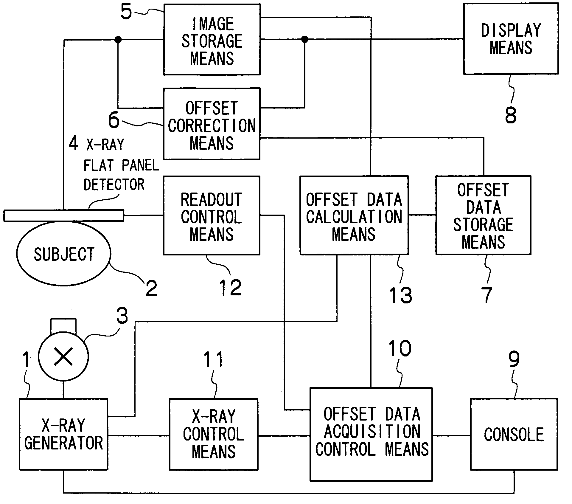
FIG. 1 is a block diagram showing a schematic configuration of the X-ray diagnosis apparatus according to the present invention. As shown in FIG. 1, the X-ray diagnosis apparatus according to the present invention includes an X-ray source 3 controlled by an X-ray generator 1 to irradiate a subject 2 with an X-ray, an X-ray flat panel detector 4 placed opposed to the X-ray source 3 for outputting X-ray image data according to the X-ray incident after passing through the subject 2, image storage means 5 for storing the X-ray image data outputted from the X-ray flat panel detector 4 as digital data, offset correction means 6 for performing offset correction to X-ray image data stored by the image storage means 5 and making the image storage means 5 again store X-ray image data after the offset correction stored by the im...


PUM


Abstract

Offset data calculation means has a normal offset data calculation function for calculating offset data based on data obtained from an X-ray flat panel detector while no X-ray is incident in each of the modes, i.e., an entire region fluoroscopy mode, a partial region fluoroscopy mode, imaging mode, etc. and storing the data in offset data storage means, and additionally has a function for updating, upon calculation of new offset data in any of the modes, another mode offset data stored in the offset data storage means based on the new offset data calculated. Thus, from offset data acquired in any of the plurality of modes, it is possible to obtain the latest offset data in all the modes.

Description

TECHNICAL FIELD The present invention relates to an X-ray diagnosis apparatus, and in particular, to a method of acquiring offset data for offset-correcting X-ray image data outputted from an X-ray flat panel detector. BACKGROUND ART In a conventional technique, an X-ray diagnosis apparatus has a configuration in which a subject is irradiated with an X-ray, and an X-ray image of the subject is displayed on a monitor, etc. based on X-ray image data outputted from an X-ray detector according to the X-ray incident on the X-ray detector after passing through the subject. The X-ray detector has variations such as an image intensifier and an X-ray flat panel detector. As for the X-ray flat panel detector, an important technology is to eliminate an offset component of a detected element channel which changes over time. For instance, an indirect X-ray flat panel detector disclosed by U.S. Pat. No. 4,689,487 is comprised of a scintillator (e.g. using cesium iodide (CsI)) for converting a...

Claims


Application Information

Patent Timeline
Patent Type & Authority Applications(United States)
IPC IPC(8): A61B6/00H04N5/32
CPCA61B6/00H04N5/32A61B6/585A61B6/583
Inventor IKEDA, SHIGEYUKI
Owner HITACHI MEDICAL CORP
Why Eureka
Try Eureka