Optical and opto-electronic interconnect alignment system

a technology of optical and opto-electronic interconnection and alignment system, which is applied in the direction of optics, optical light guides, instruments, etc., can solve the problems of loss or degradation of optical signals, excessive movement or “play” of cards, and difficulty in maintaining the leading card edge and components thereon in correct alignment with the axes of the backplane, etc., to achieve the reduction of lateral, transverse and angular ranges of motion, and the effect of reducing

Active Publication Date: 2005-04-14
3M INNOVATIVE PROPERTIES CO
View PDF28 Cites 18 Cited by
  • Summary
  • Abstract
  • Description
  • Claims
  • Application Information

AI Technical Summary

Benefits of technology

[0014] In one embodiment according to the invention, the connector alignment system comprises a base configured for mounting on a first substrate, and a housing movably engaged with the base. The housing is configured to secure an optical or opto-electronic termination, such as a terminating ferrule for an optical fiber. The housing has a longitudinal range of motion and a lateral range of motion with respect to the base. When the housing is in an unmated position, the lateral range of motion is less than the lateral range of motion when the housing is in a mated position. In another embodiment according to the invention, the housing has a transverse range of motion, and the transverse range of motion is reduced when the housing is in an unmated position. In another embodiment according to the invention, the housing has an angular range of motion, and the angular range of motion is reduced when the housing is in an unmated position. In other embodiments according to the invention, different and various combinations of lateral, transverse and angular ranges of motion are reduced when the housing is in an unmated position.

Problems solved by technology

Blind mating of a card-mounted component to a backplane connector has been found to create special challenges with regards to alignment and mating force issues along the axis of interconnection.
However, dimensional tolerances of the cards, the components thereon and the slots themselves may result in excessive movement or “play” of a card in a slot.
Thus, when an operator inserts a card in a slot, it is often difficult to maintain the leading card edge and components thereon in correct alignment with the axes of the backplane.
An optical gap will degrade the connection, resulting in the loss or degradation of the optical signals and creates undesirable internal reflecting.
On the other hand, excessive pressure on the mating faces, such as that caused by “jamming in” a card, may result in damage to the fragile optical fiber ends and mating components.
In general, designers and users of backplane connection systems find it exceedingly difficult to control the position of a card to a backplane within the precision range required for optical interconnects.
In certain instances the compressive stress may be sufficient to cause physical damage to the connector's components and the optical fibers contained therein.

Method used


Image

  • Optical and opto-electronic interconnect alignment system
  • Optical and opto-electronic interconnect alignment system
  • Optical and opto-electronic interconnect alignment system

Examples


Embodiment Construction

[0024] In the following Detailed Description, reference is made to the accompanying drawings which form a part hereof, and in which is shown by way of illustration specific embodiments in which the invention may be practiced. In this regard, directional terminology, such as “top,”“bottom,”“front,”“back,”“leading,”“trailing,” etc., is used with reference to the orientation of the Figure(s) being described. Because components of embodiments of the present invention can be positioned in a number of different orientations, the directional terminology is used for purposes of illustration and is in no way limiting. It is to be understood that other embodiments may be utilized and structural or logical changes may be made without departing from the scope of the present invention. The following detailed description, therefore, is not to be taken in a limiting sense, and the scope of the present invention is defined by the appended claims.

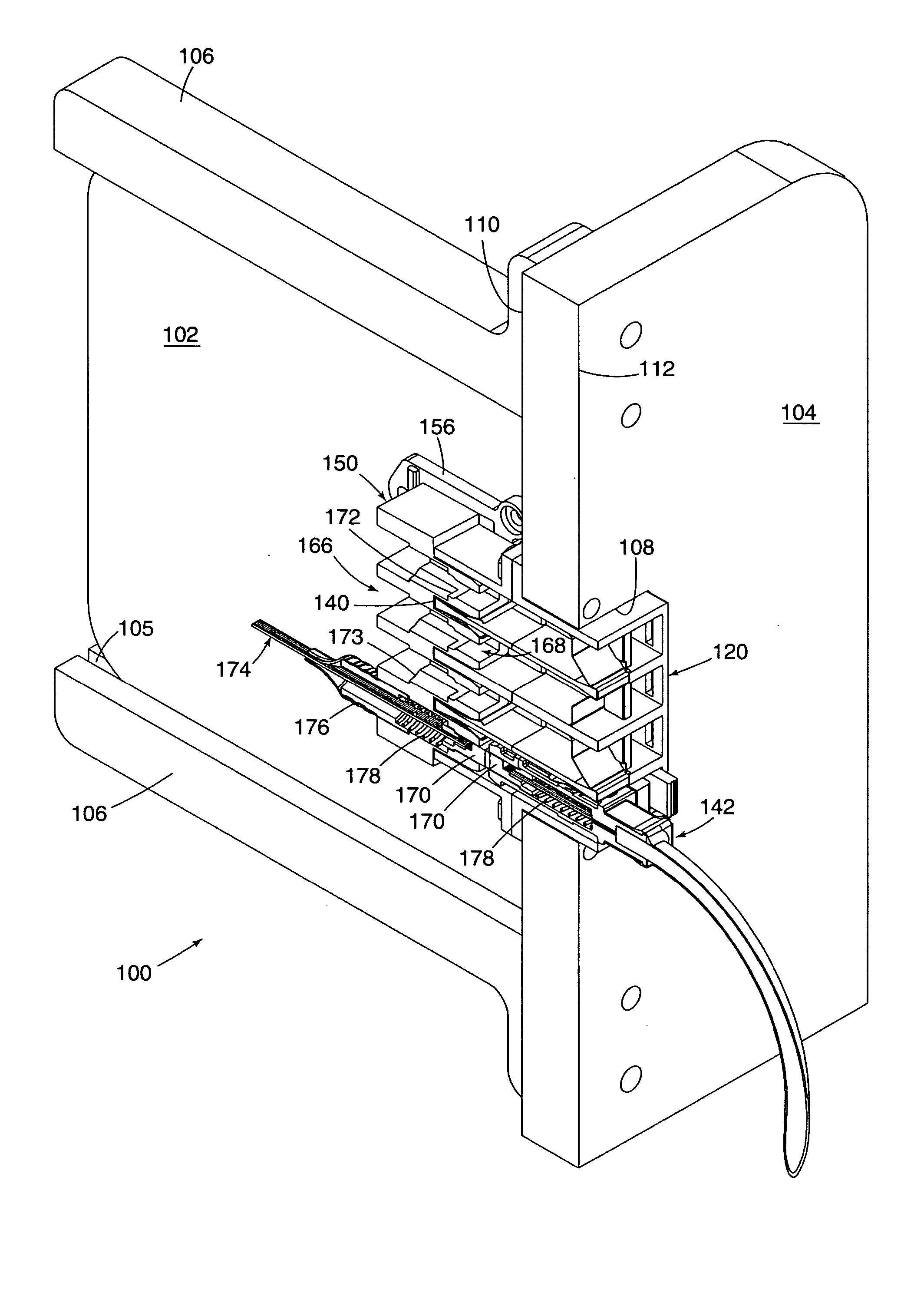
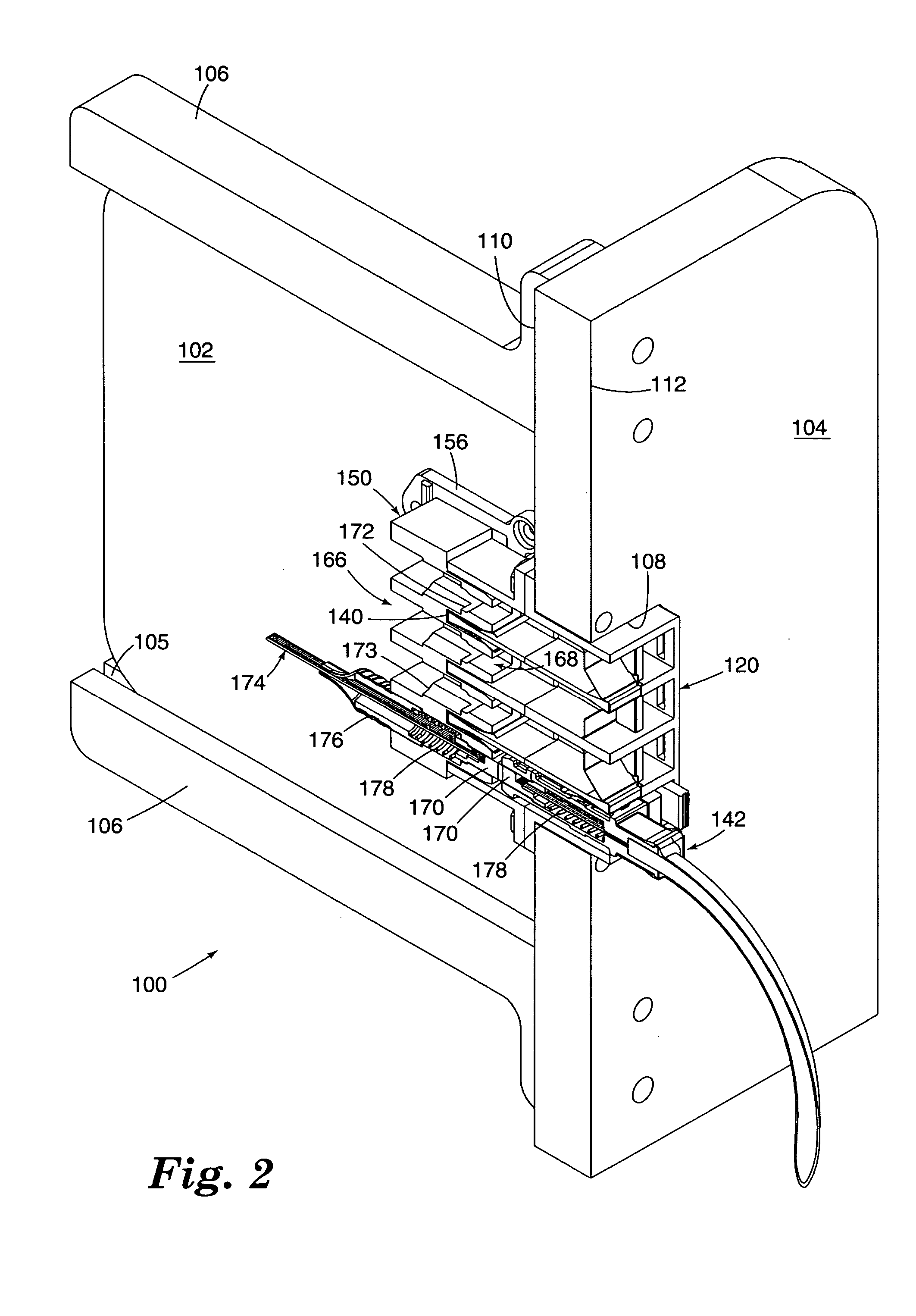
[0025]FIGS. 2 and 3 illustrate an embodiment of an i...


PUM


Abstract

A connector alignment system includes a base for mounting on a first substrate, and a housing movably engaged with the base. The housing secures an opto-electronic termination. The housing has longitudinal, lateral, transverse and angular ranges of motion with respect to the base. When the housing is in an unmated position, various combinations of the lateral, transverse and angular ranges of motion are less than the respective ranges of motion when the housing is in a mated position.

Description

BACKGROUND OF THE INVENTION [0001] The present invention relates to an interconnect alignment system for use with optical and opto-electronic systems. More particularly, the present invention relates to a device for providing alignment control during mating of an optical or opto-electronic connector system. [0002] Cabinets traditionally used for electronic devices are now being utilized to accommodate optical and opto-electronic devices. In traditional cabinet designs, the cabinet comprises a box having a plurality of internal slots (also known as racks), generally parallel to each other. Components are mounted on planar substrates (commonly referred to as circuit boards or daughter cards, or simply boards or cards) which are designed to slide into the slots within the cabinet. As a card is inserted into the slots within the cabinet, mechanical, electrical and / or optical connections are formed with mating components in the cabinet. [0003] Mating components in the cabinet are typical...

Claims


Application Information

Patent Timeline
Patent Type & Authority Applications(United States)
IPC IPC(8): G02B6/38
CPCG02B6/3821G02B6/3849G02B6/3897G02B6/3885G02B6/389G02B6/3878
Inventor COX, LARRY R.
Owner 3M INNOVATIVE PROPERTIES CO
Why Eureka
Try Eureka