Tapered fused waveguide for teeth whitening

a waveguide and waveguide technology, applied in the field of medical devices, can solve the problems of low efficiency, low efficiency, and large system size, and achieve the effects of reliable coupling and alignment characteristics, convenient making and cleaning, and convenient miniaturization

Active Publication Date: 2005-04-14
BIOLASE TECH INC
View PDF8 Cites 45 Cited by
  • Summary
  • Abstract
  • Description
  • Claims
  • Application Information

AI Technical Summary

Benefits of technology

[0011] The various embodiments of the present invention may include or address one or more of the following objectives. One objective is to provide a fiber optic coupled to an energy-distribution tuner, wherein electromagnetic radiation exiting the energy-distribution tuner is not concentrated along the fiber optic axis. The energy-distribution tuner can comprise a cylindrical reflector configured to redirect a portion of the electromagnetic radiation back toward a direction of the fiber optic axis. Another objective is to provide a bundled fiberguide having an emission characteristic whereby a power density of electromagnetic radiation exiting the bundled fiberguide is lower than a power density of electromagnetic energy entering the bundled fiberguide. Another objective is to provide a radiation emitting apparatus, which is formed to illuminate the target area with a specific illumination-area shape and / or distribution required for a particular medical or other application. The shape can be non-circular and the distribution can be uniform as measured on a non-planar surface, which can comprise, for example, an arched surface. Yet another objective is to provide an apparatus for providing uniform distributions of power density across an illumination area, with optical losses less than 10%, with a minimal number of optical components, with a simple construct that is relatively easy to make and clean, with reproducible output results, with a construct amenable to miniaturization, and / or with relatively reliable coupling and alignment characteristics. Another objective is to provide an apparatus with a relatively short length, measured in a direction normal to the target.

Problems solved by technology

In seeking to generate predetermined energy distributions, prior-art systems have implemented relatively complex optical schemes with multiple optical elements, which systems can be relatively large and / or inefficient.
Regarding efficiency, implementation of a diffuser in front of a prior-art fiber optic end together with a mirror reflector may not eliminate the “hot spot” problem and may introduce losses of laser power, which configuration can undesirably result in an efficiency as low as about 50%.

Method used


Image

  • Tapered fused waveguide for teeth whitening
  • Tapered fused waveguide for teeth whitening
  • Tapered fused waveguide for teeth whitening

Examples


Embodiment Construction

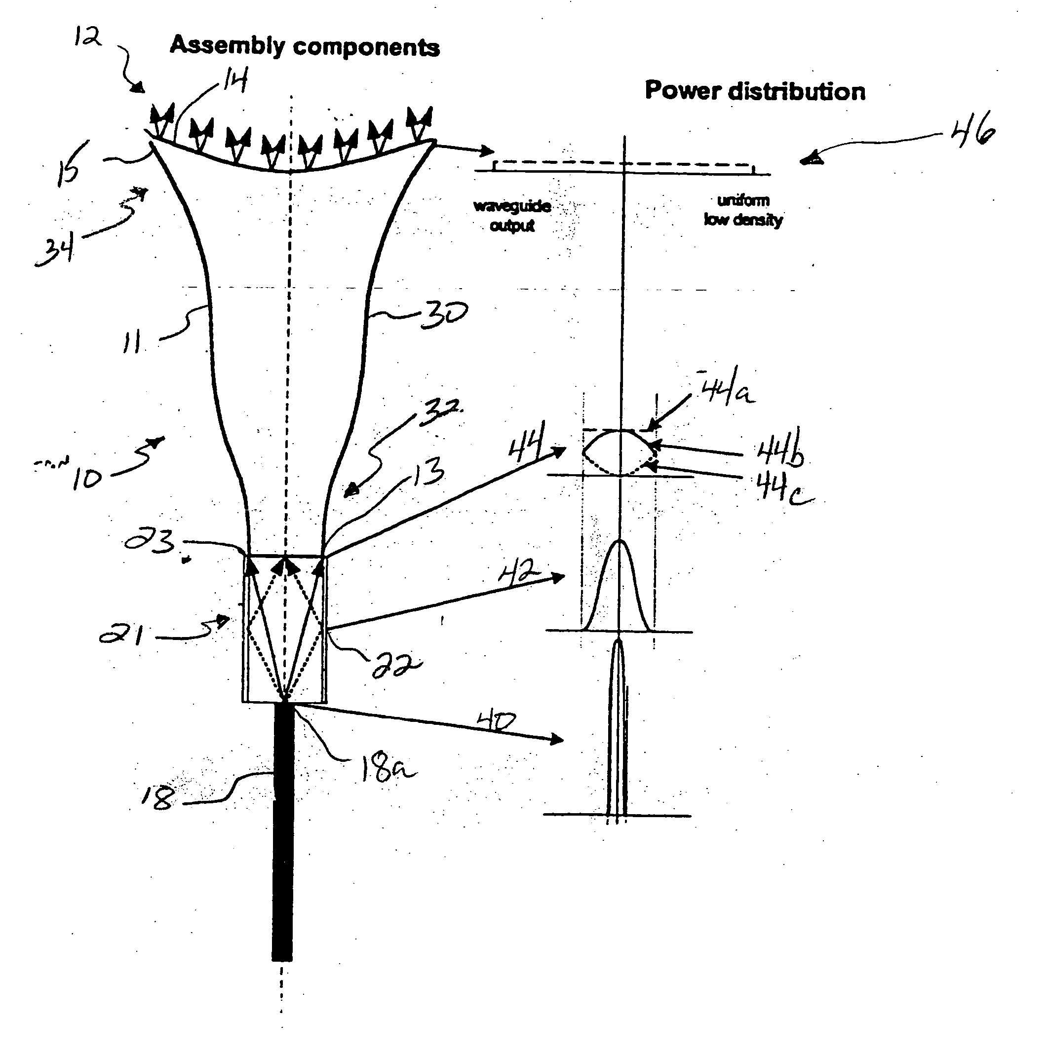
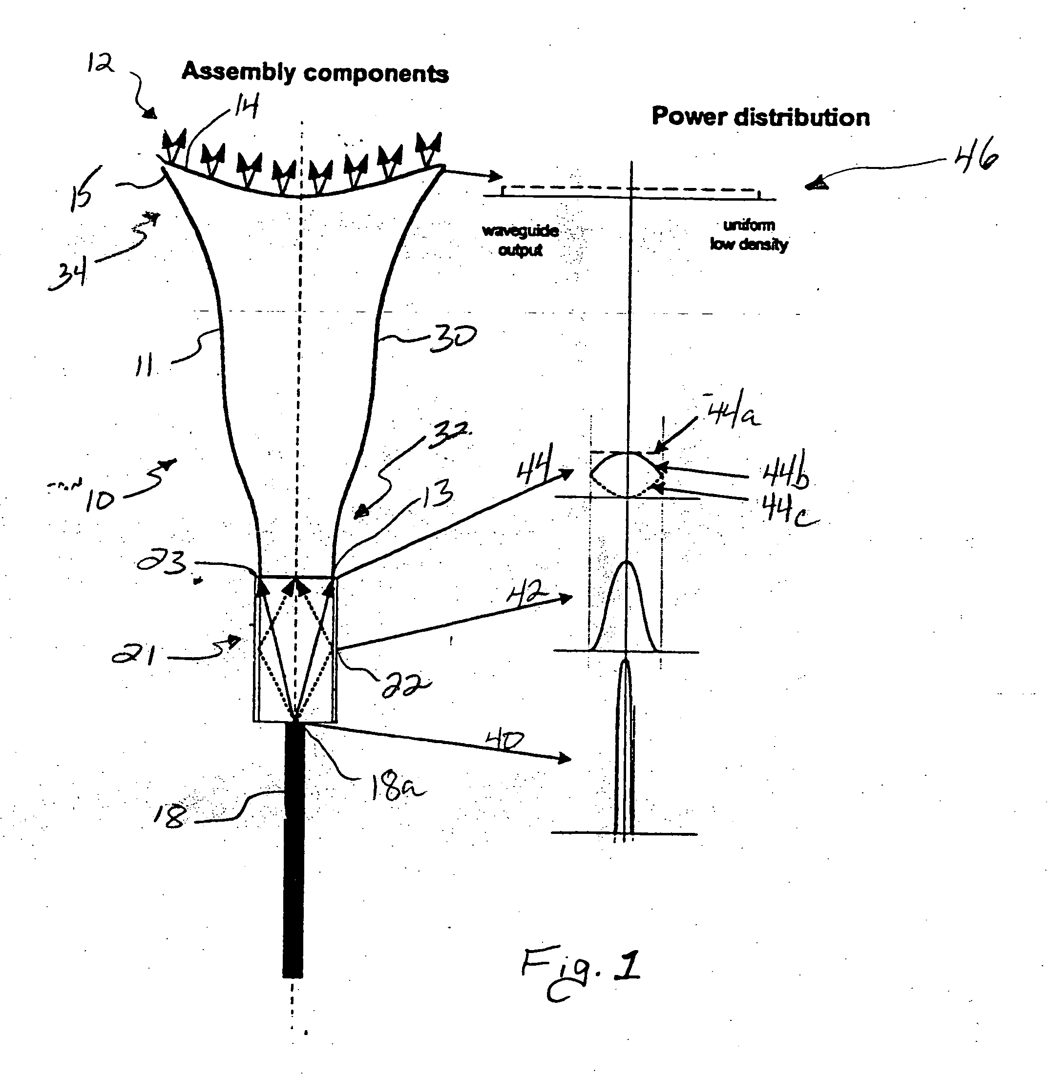
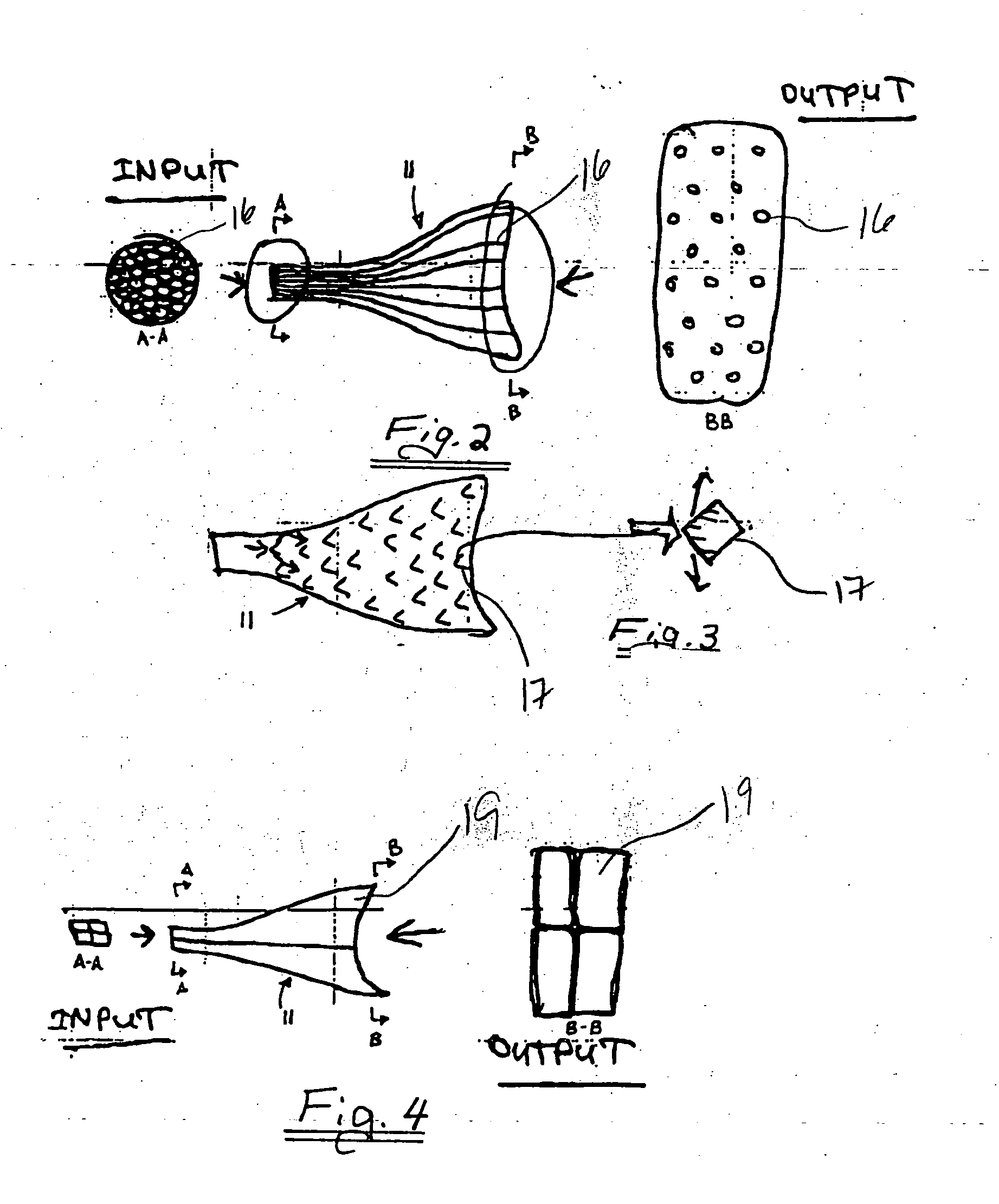
[0017] Reference will now be made in detail to certain embodiments of the invention, examples of which are illustrated in the accompanying drawings. Wherever possible, the same or similar reference numbers are used in the drawings and the description to refer to the same or like parts. It should be noted that the drawings are in simplified form and are not to precise scale. In reference to the disclosure herein, for purposes of convenience and clarity only, directional terms, such as, top, bottom, left, right, up, down, over, above, below, beneath, rear, and front, are used with respect to the accompanying drawings. Such directional terms should not be construed to limit the scope of the invention in any manner.

[0018] Although the disclosure herein refers to certain illustrated embodiments, it is to be understood that these embodiments are presented by way of example and not by way of limitation. The intent of the following detailed description, although discussing exemplary embodi...


PUM


Abstract

A radiation emitting apparatus is disclosed that emits a substantially homogenous beam of radiation from an irregularly shaped output end. As described herein, a radiation emitting apparatus includes a bundled fiberguide coupled to an energy distribution tuner. The bundled fiber guide is coupled to the energy distribution tuner to receive a substantially uniform distribution of high power energy. The bundled fiber guide is configured to distribute the energy to emit a substantially uniform distribution of lower power energy toward a target surface, such as a body surface. The bundled fiber guide may include a plurality of fused optic fibers, a plurality of beam splitting mirror elements, or tapered waveguides.

Description

CROSS-REFERENCE TO RELATED APPLICATIONS [0001] This application claims the benefit of U.S. Provisional Application Ser. No. 60 / 424,860, filed Nov. 8, 2002, and U.S. Provisional Application Ser. No. 60 / 434,585, filed Dec. 18, 2002, the entire contents of both which are incorporated herein by reference. This application is a continuation-in-part of U.S. application Ser. No. 10 / 229,374, filed Aug. 26, 2002, the entire contents of which are incorporated herein by reference.BACKGROUND OF THE INVENTION [0002] 1. Field of the Invention [0003] The present invention relates generally to medical devices and, more particularly, to laser handpieces. [0004] 2. Description of Related Art [0005] Radiation delivery systems are typically used to transport electromagnetic energy from electromagnetic energy sources to treatment sites. One common radiation delivery system can comprise a cylindrically-shaped fiber optic tip from which electromagnetic energy is emitted in a direction toward the treatment...

Claims


Application Information

Patent Timeline
Patent Type & Authority Applications(United States)
IPC IPC(8): A61B18/22A61C19/06
CPCA61B18/22A61C19/066A61B2018/2261A61B18/203A61B2018/2205A61C1/0046A61N5/0613A61N2005/0643
Inventor JONES, JEFFREY W.BOUTSOUSSOV, DMITRI
Owner BIOLASE TECH INC
Why Eureka
Try Eureka