
Breakaway support for overhead lines

a technology for overhead lines and breakaway supports, which is applied in the direction of machine supports, couplings, manufacturing tools, etc., can solve the problems of breakaway support failure, structural component failure, crossarm snapping, etc., and achieve the effect of reducing the stress produced in the weak link, increasing the footprint, and reducing the stress in the weak link

Inactive Publication Date: 2005-04-21
MCDONALD RICHARD ALAN
View PDF18 Cites 16 Cited by
  • Summary
  • Abstract
  • Description
  • Claims
  • Application Information

AI Technical Summary

Benefits of technology

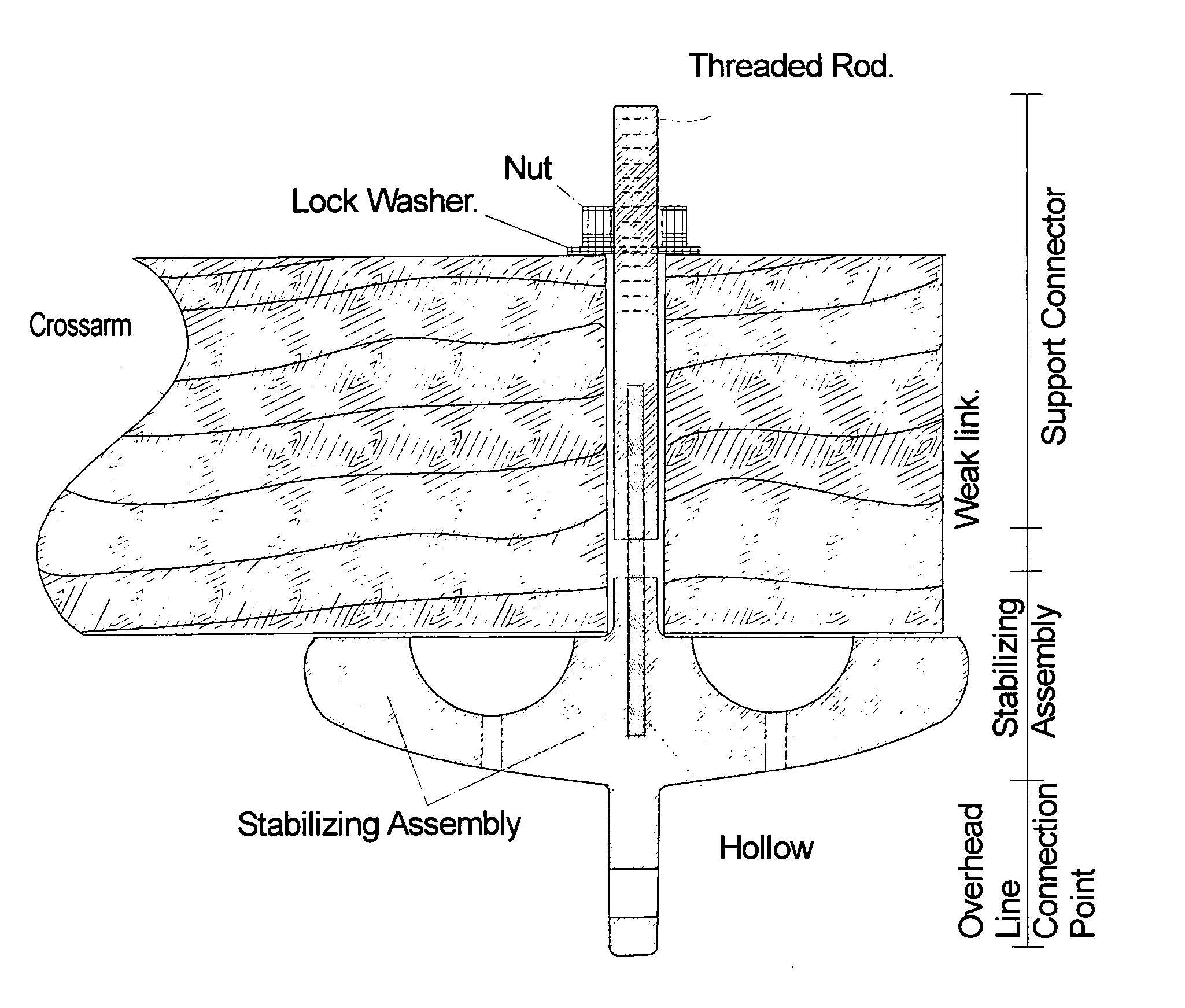
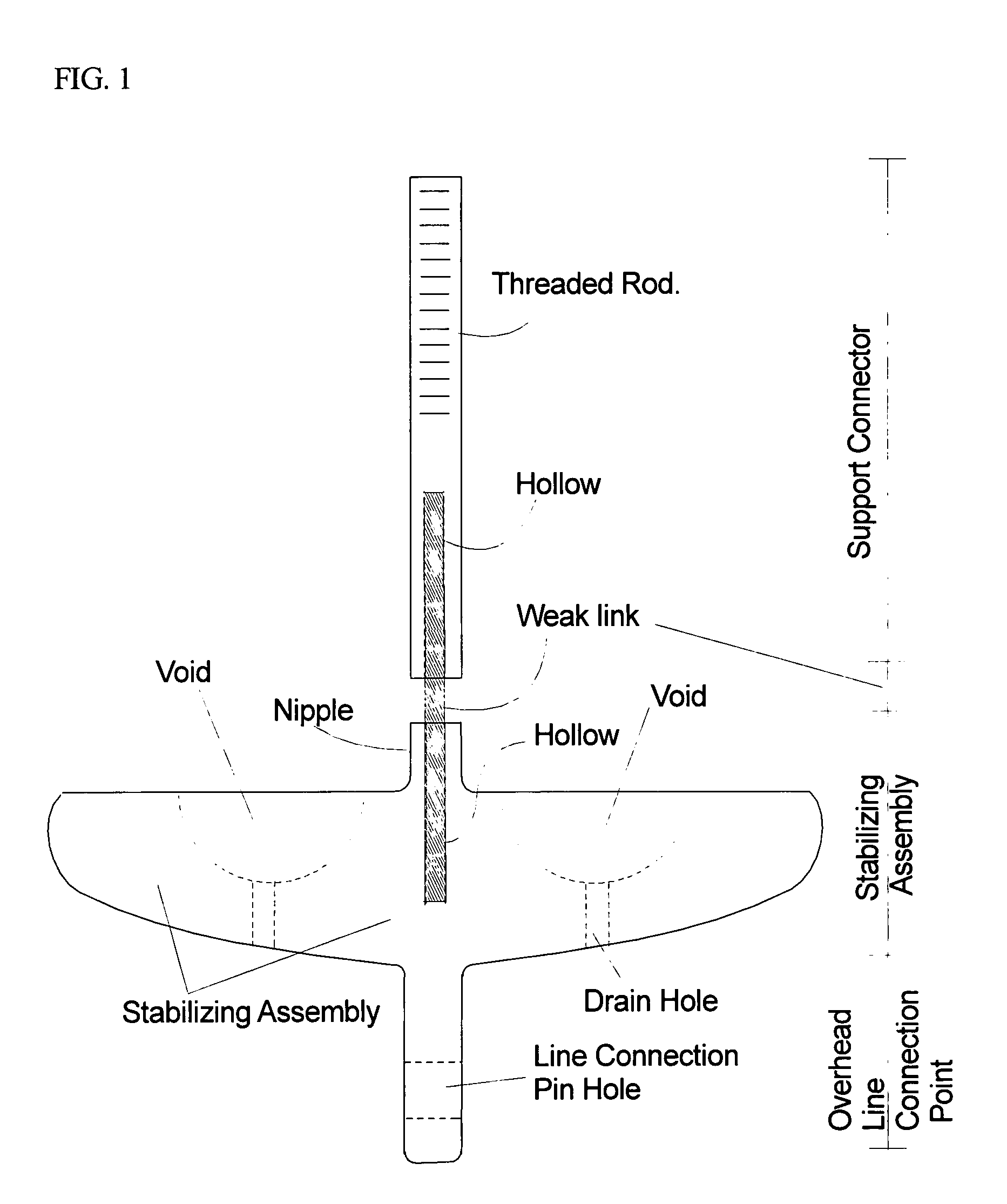
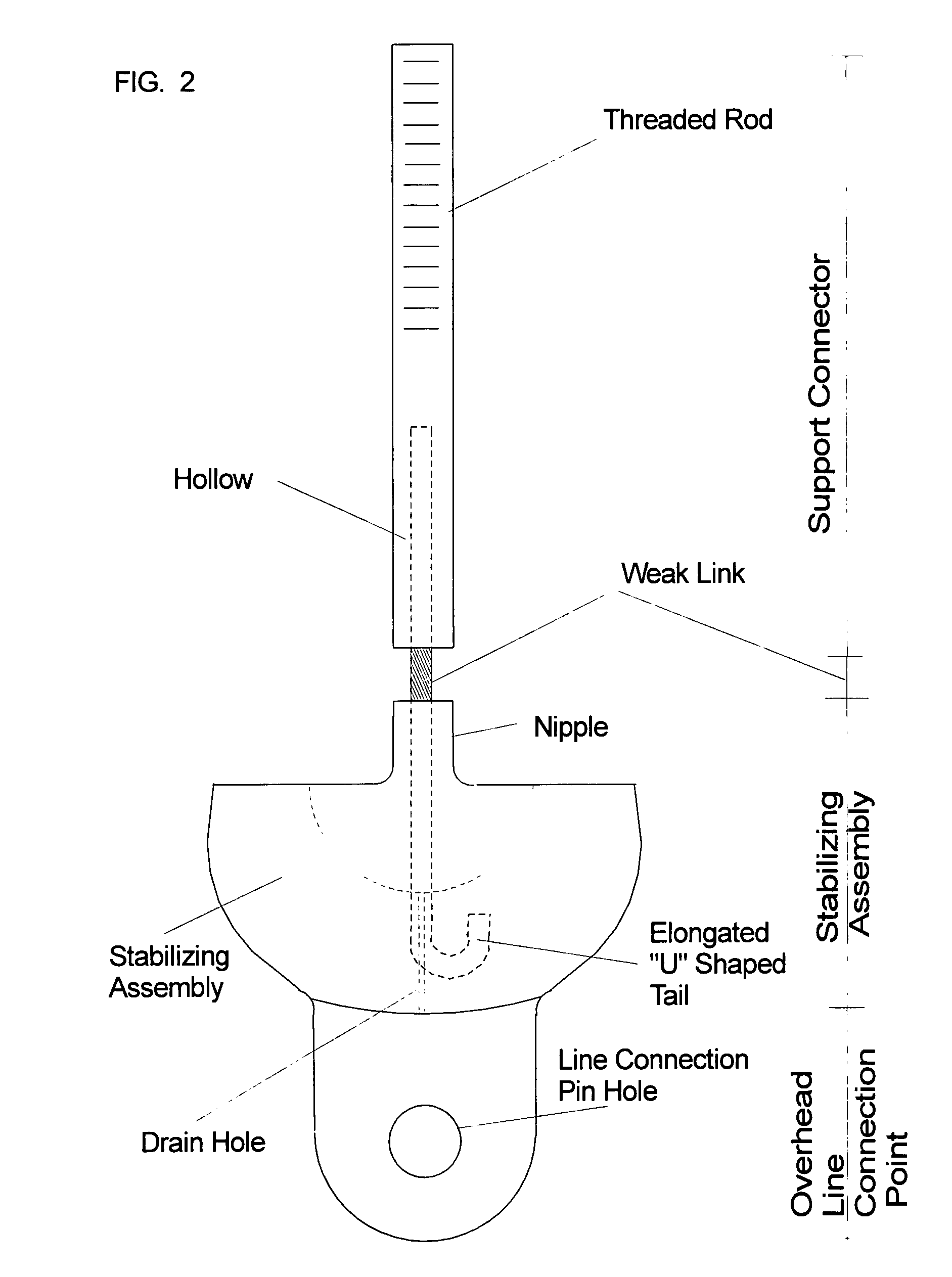
[0008] The objective of the breakaway support for overhead lines is to provide a low cost, easy to install, all weather, structurally coordinated overhead line release system. The result of the objective is a quicker and less costly restoration of service for the group maintaining the overhead lines. When the overhead line is exposed to some from of trauma (tree, wind, ice, etc.) the main structural components (poles, towers, crossarms, etc.) should not fail. The present design often results in a structural component failure. Poles break, crossarms snap, towers crumble. The breakaway support for overhead lines prevents damage to the overall system. Only the breakaway support fails. Maintenance crews can clear the line from the trauma (tree, ice, etc.), replace the breakaway support and reattach the line to the undamaged structure. The crews do not have to replace the supporting structure (poles, towers, crossarms, etc.).
[0012] The other end of the weak link is connected to the stabilizing assembly. The nipple on the stabilizing assembly is hollowed out and the other end of the weak link is inserted into the stabilizing assembly. The stabilizing assembly provides (1) protection for the weak link. The breakaway support for overhead lines is usually inserted in a hole drilled or formed in the supporting structure. The nipple on the stabilizing assembly prevents the weak link from rubbing on the inside of the hole in the support structure. The nipple on the stabilizing assembly prevents the strands of the weak link from being damaged. The stabilizing assembly also (2) provides structural support. The breakaway support for overhead lines obviously supports the overhead lines. These overhead lines can be exposed to sever transverse (wind, truck striking line, etc.) loads. These transverse loads on the end of an electric insulator produce a moment. The increased footprint provided by the stabilizing assembly will lower the stress produced in the weak link. For a given transverse load the stresses in the weak link will be lower for a stabilizing assembly with a large footprint than for a stabilizing assembly with a small footprint. As such the breakaway support for overhead lines must be engineered for each application. One design can be used at hundreds of similar locations.
[0013] Physically connected to the stabilizing assembly is the overhead line connection point. The overhead line connection point provides a point-of-attachment for an electric insulator or a connector which is then connected to the overhead line (multi-conductor communications line, fiber optic line, individual or multi-stranded power lines, etc.). The connection point will provide resistance to lateral line movement cause by wind and other forces. The connection point will provide resistance to the effects of galloping conductors. When a fault occurs on an electric line, there is a large current surge. A large current surge produces a large magnetic field. When a phase to phase fault occurs we have two large magnet fields that are produced. The magnetic fields cause the conductors to sway. The swaying conductors may make contact and cause their own fault. The design and orientation of the overhead line connection point will help dampen the galloping conductors.

Problems solved by technology

The present design often results in a structural component failure.
Poles break, crossarms snap, towers crumble.
Only the breakaway support fails.
Existing devices are limited to low voltage lines.
Their design ensures that communication service will be lost.

Method used


Image

  • Breakaway support for overhead lines
  • Breakaway support for overhead lines
  • Breakaway support for overhead lines

Examples


Embodiment Construction

[0024] An exhaustive search of existing patents failed to identify a product that provides the advantages that the breakaway support for overhead lines provides. Likewise an industry search failed to identify a product that competes with the breakaway support for overhead lines. At least one type of breakaway device has a United States patent. This device (U.S. Pat. No. 5,315,064) is for low voltage (600v or less) application. In order to work successfully, this device requires the service connection to be broken. The breakaway support for overhead lines can work on both high and low voltage electrical lines. Furthermore the breakaway support for overhead lines does not require the service connection to be broken. Lower voltage communications conductors can remain on the ground and continue to provide service to their clients. Furthermore the breakaway support for overhead lines addresses the concern of transverse loading (primarily wind load though other loads are conceivable). A l...


PUM


Abstract

The breakaway support for overhead lines is a coordinated failure control device. The breakaway support for overhead lines sacrifices itself to ensure that the supporting structure is not damaged. The device has an intentional weak link. The breakaway support for overhead lines will release when the overhead line it is supporting receives a stress that exceeds the tensile strength of the weak link in the breakaway support for overhead lines. The stress causes the weak link to fail. The structure is not damaged and a repair crew can quickly affect repairs. It is much cheaper and easier to reconnect an overhead line than it is to replace or repair a structure and then reconnect the overhead line.

Description

CROSS-REFERENCE TO RELATED APPLICATIONS [0001] Some of the background information was taken from U.S. Pat. No. 6,197,545 filed by Fanucce, Jerome P. and Gorman, James J. on Jun. 4, 2002. U.S. Pat. No. 5,315,064 filed by Andrews, Dean D. on Nov. 8, 1991 was also reviewed. The main purpose of the review was to differentiate this patent application from U.S. Pat. No. 5,315,064. (more simplistic design, designed for high and low voltages, uninterrupted service).STATEMENT REGARDING FEDERALLY SPONSORED RESEARCH OR DEVELOPMENT [0002] This patent application and the work associated with it were in no way, shape nor form funded or sponsored directly or indirectly by any state, federal or foreign government or entity. REFERENCE TO SEQUENCE LISTING [0003] Not Applicable. BACKGROUND OF THE INVENTION [0004] Background: This Breakaway Support for Overhead Lines is an apparatus that is specifically used to mount insulators and overhead lines to structures (poles, towers, crossarm, etc.).1 The obje...

Claims


Application Information

Patent Timeline
Patent Type & Authority Applications(United States)
IPC IPC(8): E04B1/00H02G7/02
CPCY10T403/604H02G7/02
Inventor MCDONALD, RICHARD ALAN
Owner MCDONALD RICHARD ALAN
Learn More