
Combined cycle engines incorporating swirl augmented combustion for reduced volume and weight and improved performance

a combined cycle and engine technology, applied in the field of combined cycle engines, can solve the problems of large combustor length, large combustor length, and inefficient construction of the ramjet engine combustor, and achieve the effects of reducing the length of the combustor, vaporizing and mixing, and rapid fuel atomization

Inactive Publication Date: 2005-04-21
UNITED TECH CORP +1
View PDF25 Cites 29 Cited by
  • Summary
  • Abstract
  • Description
  • Claims
  • Application Information

AI Technical Summary

Benefits of technology

[0010] The present invention overcomes the aforementioned drawbacks by providing a combined-cycle engine having a ramjet engine having a swirl generator that causes extremely rapid fuel atomization, vaporization and mixing with a combustion efficiency that ranges from about 90% to about 99%. Consequently, we were able to reduce the length of the combustor to attain L / D ratios substantially less than that which was attained by any known combustors.

Problems solved by technology

The capability of an aircraft to fly at hypersonic speeds places significant demands on the aircraft's propulsion system, since the aircraft must also fly slow enough to land and produce thrust for take off when the aircraft has zero velocity.
One drawback associated with the known combined cycle engines concerns the construction of the combustor that is used by the ramjet engine.
More specifically, the combustors that are employed by the known combined cycle engines are relatively inefficient, heavy and large, usually having a length-to-diameter (L / D) ratio of about 5.0 to about 3.0.

Method used


Image

  • Combined cycle engines incorporating swirl augmented combustion for reduced volume and weight and improved performance
  • Combined cycle engines incorporating swirl augmented combustion for reduced volume and weight and improved performance
  • Combined cycle engines incorporating swirl augmented combustion for reduced volume and weight and improved performance

Examples


Embodiment Construction

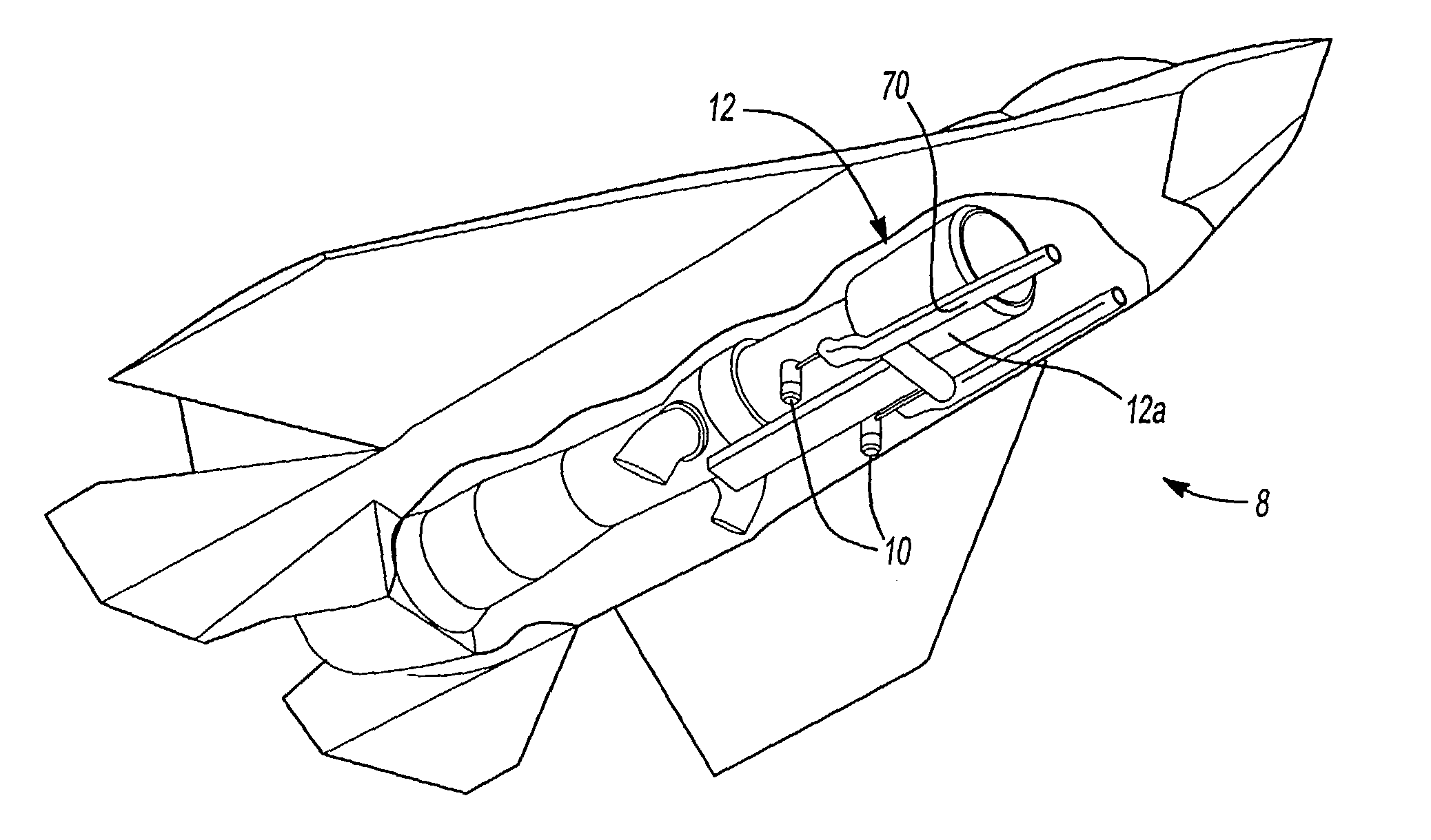
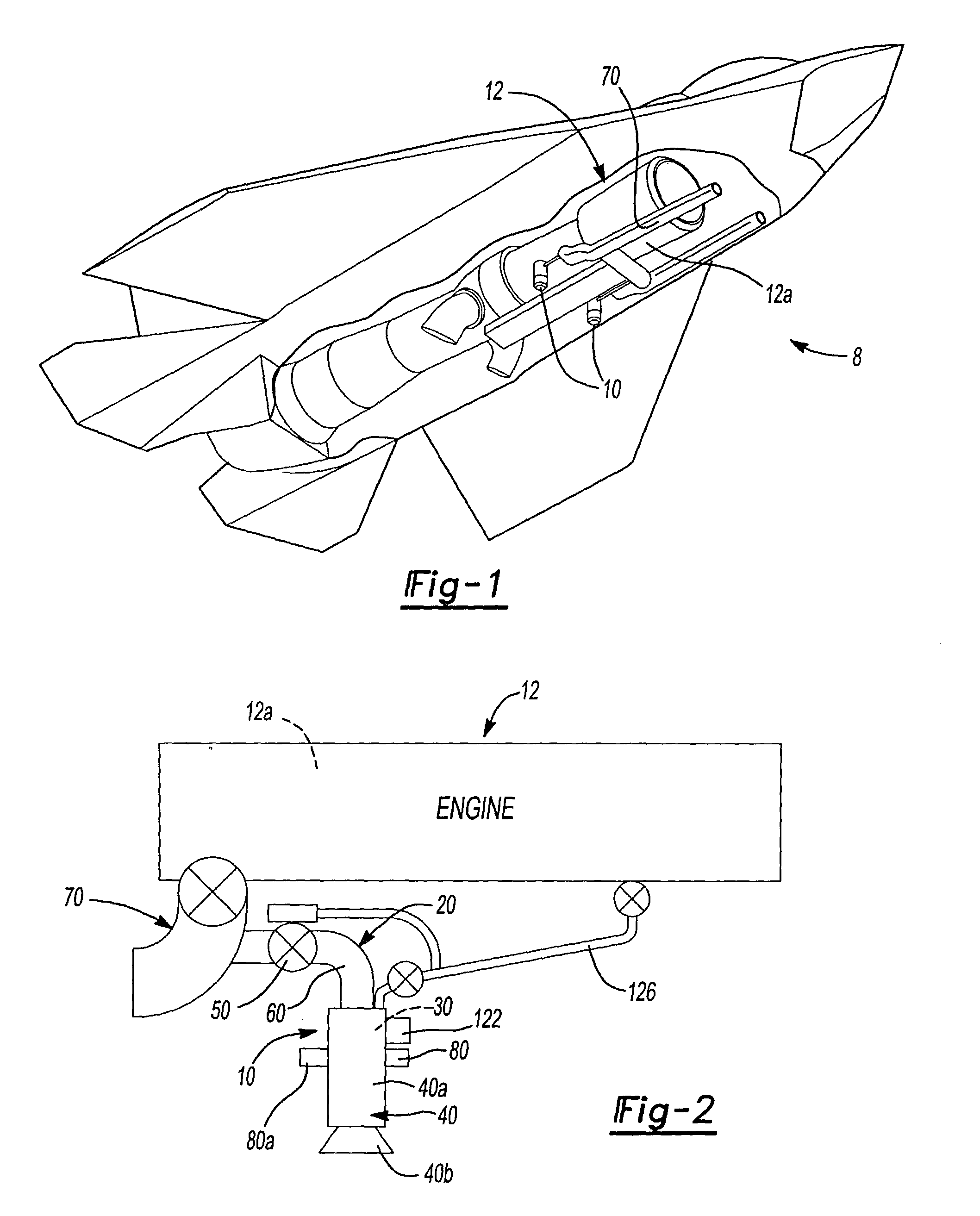
[0060] With reference to FIG. 1 of the drawings, an exemplary jet aircraft 8 is illustrated to include a pair of lift thrust augmentors 10 that are constructed in accordance with the teachings of the present invention. A conventional gas turbine engine 12 serves as the primary source of propulsive power for the jet aircraft 8, while the lift thrust augmentors 10 are selectively operable to produce thrust when the demand for thrust exceeds a predetermined threshold.

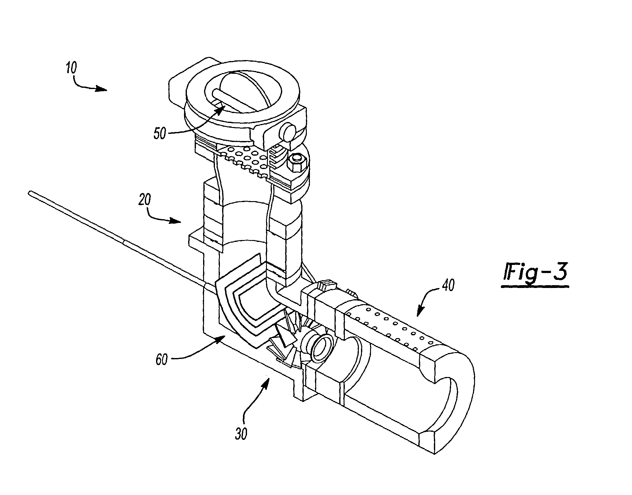
[0061] With additional reference to FIGS. 2 through 4, each lift thrust augmentor 10 includes an air delivery portion 20, a swirl generator 30 and a combustor / nozzle portion 40. When combined, the swirl generator 30 and combustor / nozzle portion 40 are also known as a compact swirl-augmented thruster (COSAT). The air delivery portion 20 includes a butterfly valve 50 and in the particular example provided, an elbow 60. It will be readily apparent to those skilled in the art that the air delivery portion 20 may be configured...


PUM


Abstract

A combined-cycle engine having at least one core engine and at least one ramjet engine. The ramjet utilizes a novel swirl generator for rapidly and efficiently atomizing, vaporizing, as necessary, and mixing a fuel into an oxidant. The swirl generator converts an oxidant flow into a turbulent, three-dimensional flowfield into which the fuel is introduced. The swirl generator effects a toroidal outer recirculation zone and an inner central recirculation zone, both of which are configured in a backward-flowing manner that carries heat and combustion byproducts upstream where they are employed to continuously ignite a combustible fuel / oxidizer mixture in adjacent shear layers, which accelerate flame propagation throughout the core flowfield. The swirl generator provides smooth combustion with no instabilities and minimum total pressure losses and enables significant reductions in the L / D ratio of the combustor. Other benefits include simplicity, reliability, wide flammability limits, high combustion efficiency and high specific thrust performance.

Description

CROSS-REFERENCE TO RELATED APPLICATIONS [0001] This application is a continuation-in-part of U.S. application Ser. No. 10 / 243,961, filed Sep. 13, 2002 entitled “Compact, Lightweight High-Performance Lift Thruster Incorporating Swirl-Augmented Oxidizer / Fuel Injection Mixing and Combustion”. Other features of the present invention are discussed and claimed in copending U.S. application Ser. No. ______ entitled “Compact Lightweight Ramjet Engines Incorporating Swirl Augmented Combustion With Improved Performance and in copending U.S. application Ser. No. ______ entitled “Compact Swirl Augmented Afterburners for Gas Turbine Engines”.FIELD OF THE INVENTION [0002] The present invention generally relates to combined-cycle engines and more particularly to a combined cycle engine having an improved fuel / oxidizer mixing and combustion apparatus. BACKGROUND OF THE INVENTION [0003] The capability of an aircraft to fly at hypersonic speeds places significant demands on the aircraft's propulsion ...

Claims


Application Information

Patent Timeline
IPC IPC(8): B64D27/20F02C7/042F02K7/16F02K7/18F23C7/00F23C9/00F23R3/14F23R3/20F23R3/22F23R3/28
CPCF02K7/16F02K7/18F23C7/006F23C9/006F23C2900/09002Y02T50/675F23R3/20F23R3/22F23R3/286Y02T50/672F23R3/14Y02T50/60
Inventor EDELMAN, RAYMOND B.MORRISON, CALVIN Q. JR.PEDERSON, ROBERT J.MORRIS, DONALD H.SCHMOTOLOCHA, STEPHEN N.
Owner UNITED TECH CORP
Learn More