Atomic force microscope and method for determining properties of a sample surface using an atomic force microscope

a technology of atomic force microscope and sample surface, which is applied in the direction of mechanical measuring arrangement, mechanical roughness/irregularity measurement, instruments, etc., can solve the problems of rapidly worn tip and damage to sample, and achieve the effect of reducing the wear of the tip

Active Publication Date: 2005-04-21
IBM CORP
View PDF3 Cites 31 Cited by
  • Summary
  • Abstract
  • Description
  • Claims
  • Application Information

AI Technical Summary

Benefits of technology

[0008] An object of the present invention is to provide an atomic force microscope and method for determining properties of a sample surface using an atomic force microscope that reduces tip wear.

Problems solved by technology

This causes the tip to wear out rapidly, usually after only a few contacts.
Further, the downward force on the tip required to maintain electrical contact between the tip and the sample surface can damage the sample.

Method used


Image

  • Atomic force microscope and method for determining properties of a sample surface using an atomic force microscope
  • Atomic force microscope and method for determining properties of a sample surface using an atomic force microscope

Examples


Embodiment Construction

[0017] In the method of performing atomic force microscopy according to various exemplary embodiments of the invention, a probe is lowered in contact with the surface of a sample until current begins to flow between the probe and the sample. A magnetic field is then applied to the probe and sample. The magnetic field is oscillated rapidly, causing the AFM probe to move such that the probe makes excellent stable contact with the surface of the sample. Probe wear is reduced because the probe does not need to be forcefully pushed onto the surface to initiate and maintain electrical contact.

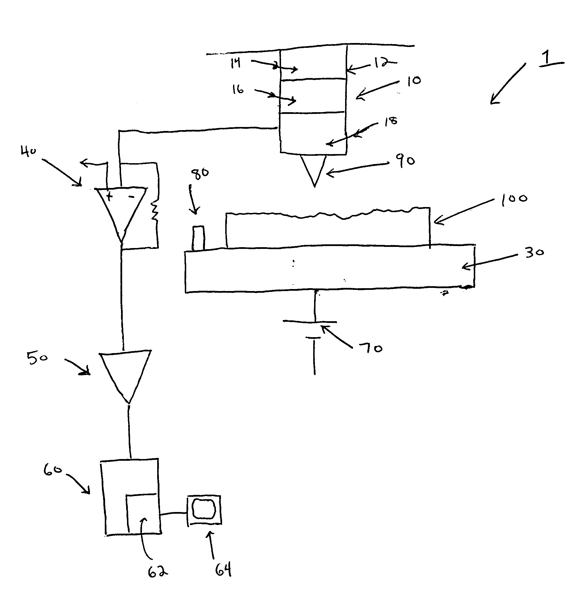
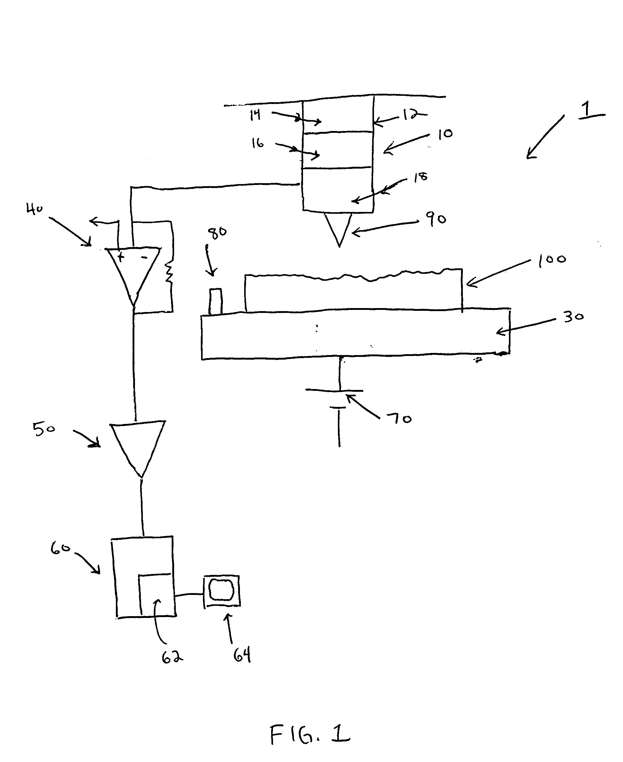
[0018]FIG. 1 shows an atomic force microscope according to an exemplary embodiment of the invention. The atomic force microscope 1 includes a piezoelectric scanner 10, a stage 30, a current-to-voltage converter 40, an amplifier 50, a controller 60, a voltage source 70 and a magnetic field source 80. The piezoelectric scanner 10 includes a piezoelectric tube 12. The piezoelectric tube 12 includes an ...


PUM


Abstract

A method for determining properties of a sample surface using an atomic force microscope includes applying a first voltage between the sample and a probe, moving the probe towards the surface of the sample, and stopping movement of the probe towards the surface of the sample when current in the probe is initially detected. An oscillating magnetic field is applied to the probe such that the probe obtains stable contact with the surface of the sample.

Description

GOVERNMENT FUNDING [0001] Funding for this invention was provided by the U.S. Government under DARPA contract number MDA972-99-C-0009BACKGROUND OF THE INVENTION [0002] 1. Field of the Invention [0003] The present invention relates to conductive probe microscopes, and more particularly to atomic force microscopes. [0004] 2. Description of the Related Art [0005] Scanning probe microscopy, such as conductive atomic force microscopy (CAFM), is widely used for observing and analyzing sample surfaces in the atomic scale. One conventional example of an atomic force microscope (AFM) uses a probe that has a microfabricated tip mounted on a flexible cantilever. The tip is typically made from Si3N4 or Si. The tip is slowly scanned across the surface of a material, just a few angstroms away from the surface (non-contact mode) or in contact with it (contact mode). The force between the atoms on the surface of the material and those on the tip cause the tip to deflect. The magnitude of the deflec...

Claims


Application Information

Patent Timeline
Patent Type & Authority Applications(United States)
IPC IPC(8): G01B5/28G01Q10/00G01Q10/06G01Q60/24G01Q60/30
CPCB82Y35/00G01Q60/30G01Q10/06
Inventor WORLEDGE, DANIEL
Owner IBM CORP
Why Eureka
Try Eureka