Two dimensional phased arrays for volumetric ultrasonic inspection and methods of use

a phased array and ultrasonic inspection technology, applied in the direction of mechanical vibration separation, instruments, specific gravity measurement, etc., can solve the problems of reducing the volume of the test material that is interrogated, the time involved in setting up and scanning the entire set, and the difficulty in accommodating for surface curvature or other complex geometry on the surface of the test pi

Active Publication Date: 2005-04-21
GENERAL ELECTRIC CO
View PDF8 Cites 35 Cited by
  • Summary
  • Abstract
  • Description
  • Claims
  • Application Information

AI Technical Summary

Problems solved by technology

However, in addition to these benefits, the reduction in insonified material volume also reduces the volume of test material that is interrogated by each ultrasonic pulse.
The primary drawback to such a technique is the time involved in setting up and scanning the entire set of zones for the given volume of material under test.
An additional drawback is the difficulty in accommodating for surface curvature or other complex geometry o...

Method used


Image

  • Two dimensional phased arrays for volumetric ultrasonic inspection and methods of use
  • Two dimensional phased arrays for volumetric ultrasonic inspection and methods of use
  • Two dimensional phased arrays for volumetric ultrasonic inspection and methods of use

Examples


Embodiment Construction

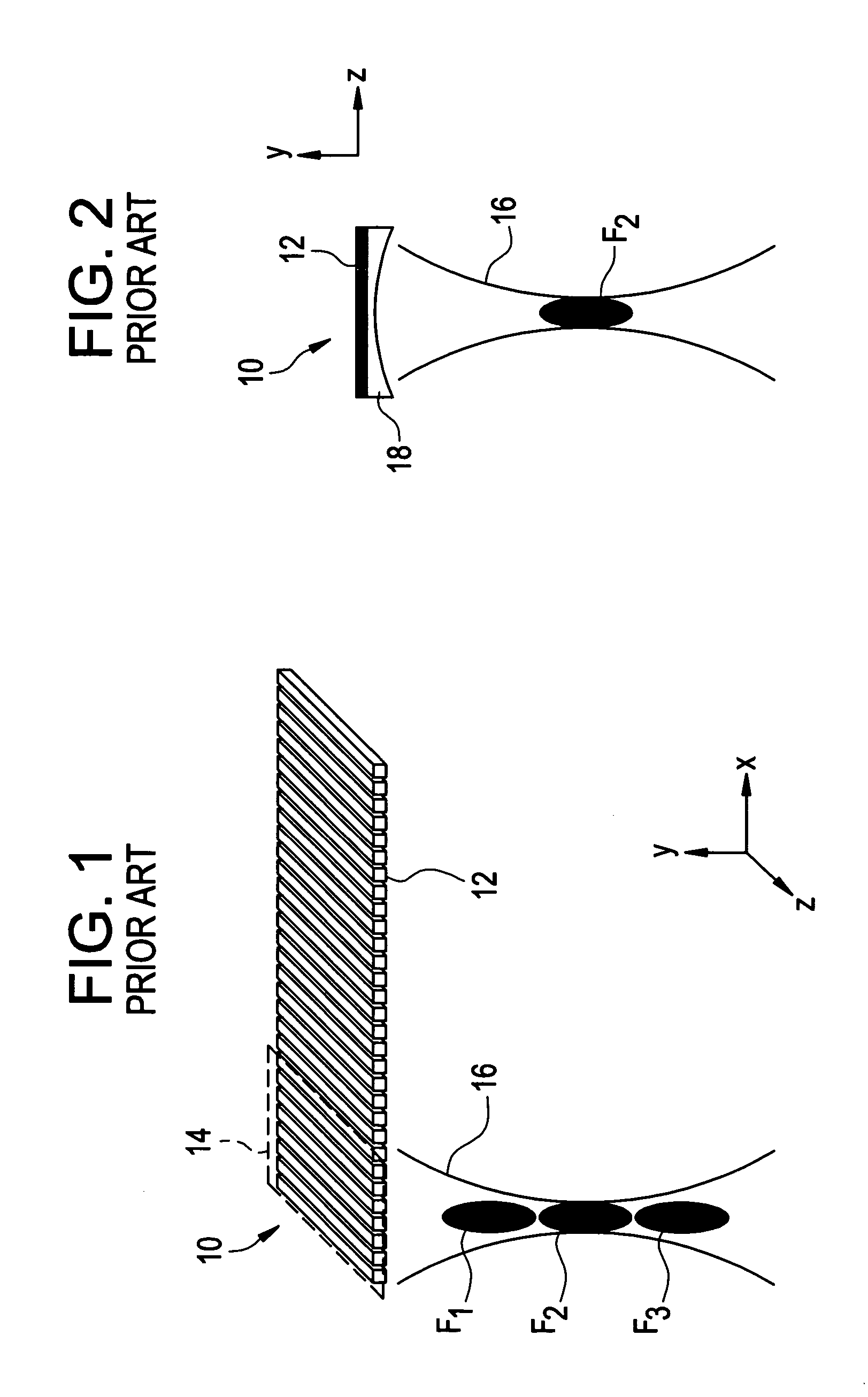
[0021] Referring initially to FIGS. 1 and 2, a prior art one-dimensional phased array is designated generally at numeral 10. As seen in FIG. 1, phased array 10 includes a linear array of transducers 12 extending in an X direction (i.e., an azimuthal direction). Each transducer 12 is typically one quarter to several wavelengths in width in the azimuthal direction and tens or hundreds of acoustic wavelengths in width in a Z direction (i.e., an elevational direction).

[0022] Array 10 is configurable to define a plurality of apertures 14 by electronically addressing and subsequently firing a group of elements. For illustrative purposes a single aperture 14 is identified by the indicated region of FIG. 1. Aperture 14 of array 10 typically has a fixed dimension in the Z direction equal to the elevational width of the transducers 12 and a variable dimension in the X direction directly related to the number of transducers 12 activated during the particular shot. Aperture 14 is configured an...


PUM


Abstract

The present disclosure provides for the application of a two-dimensional ultrasonic phased array (100), formed of a plurality of transducers (102) arranged in a rectilinear pattern, for material and volumetric component testing. The two-dimensional array enables electronic adjustment of the focal properties and size of the aperture in both the azimuthal and elevational directions such that uniform and/or specified sound field characteristics can be obtained at any or all locations in the component being tested.

Description

BACKGROUND [0001] The present invention relates to phased array ultrasonic inspection, and more particularly to a novel two dimensional phased array transducer and inspection method for the non-destructive evaluation of the volume of a material or test piece using focused ultrasonic beams. [0002] When inspecting and / or testing materials which produce a degree of back scattering, such as, for example, titanium, steel or nickel-base super alloys, focusing of the ultrasonic inspection beam enhances the back-reflected signal from flaws contained in the test material and also reduces the noise produced by the test material. This improves the signal to noise ratio (SNR) for all ultrasonic indications, and in turn improves the capability of detecting flaws and the probability of detection (POD), allowing for the detection of flaws having reflectivities equivalent to #1 ({fraction (1 / 64)}″) or #2 ({fraction (2 / 64)}″) flat bottom holes. Such inspections are often required for aircraft materi...

Claims


Application Information

Patent Timeline
IPC IPC(8): B06B1/06G01N29/24G01N29/26G01S7/52G01S15/89G10K11/34H04R17/00
CPCG01N29/262G01N2291/106G10K11/346G01S15/8925G01N2291/2693
Inventor BARSHINGER, JAMES NORMANBATZINGER, THOMAS JAMESLI, WEIDEATON, JOHN BRODDUS JR.LAPPAS, DAVID PAULGILMORE, ROBERT SNEEKLAASSEN, RICHARD EUGENE
Owner GENERAL ELECTRIC CO
Why Eureka
Try Eureka