Fuel container with reticulated material

a technology of reticulated materials and fuel containers, which is applied in the direction of transportation and packaging, electrical equipment, mechanical equipment, etc., can solve the problems of high power applications, undesirable anode products, and high processing costs of fuel processing, so as to prevent undesired fuel flow, reduce undesired leakage, and facilitate delivery

Inactive Publication Date: 2005-04-21
MTI MICROFUEL CELLS
View PDF9 Cites 5 Cited by
  • Summary
  • Abstract
  • Description
  • Claims
  • Application Information

AI Technical Summary

Benefits of technology

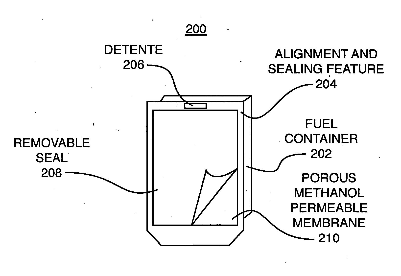
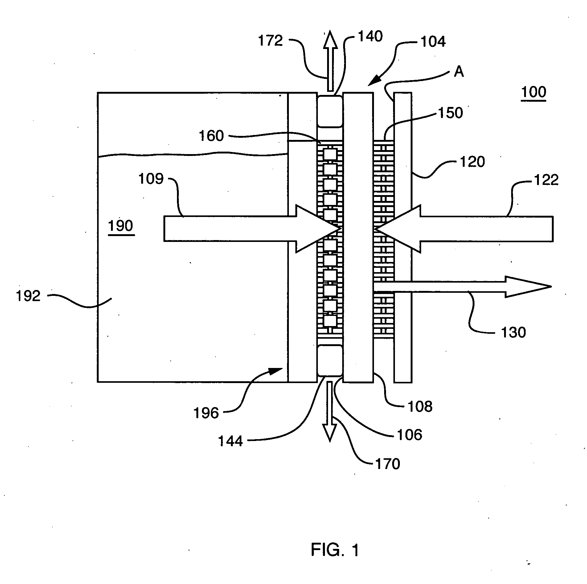
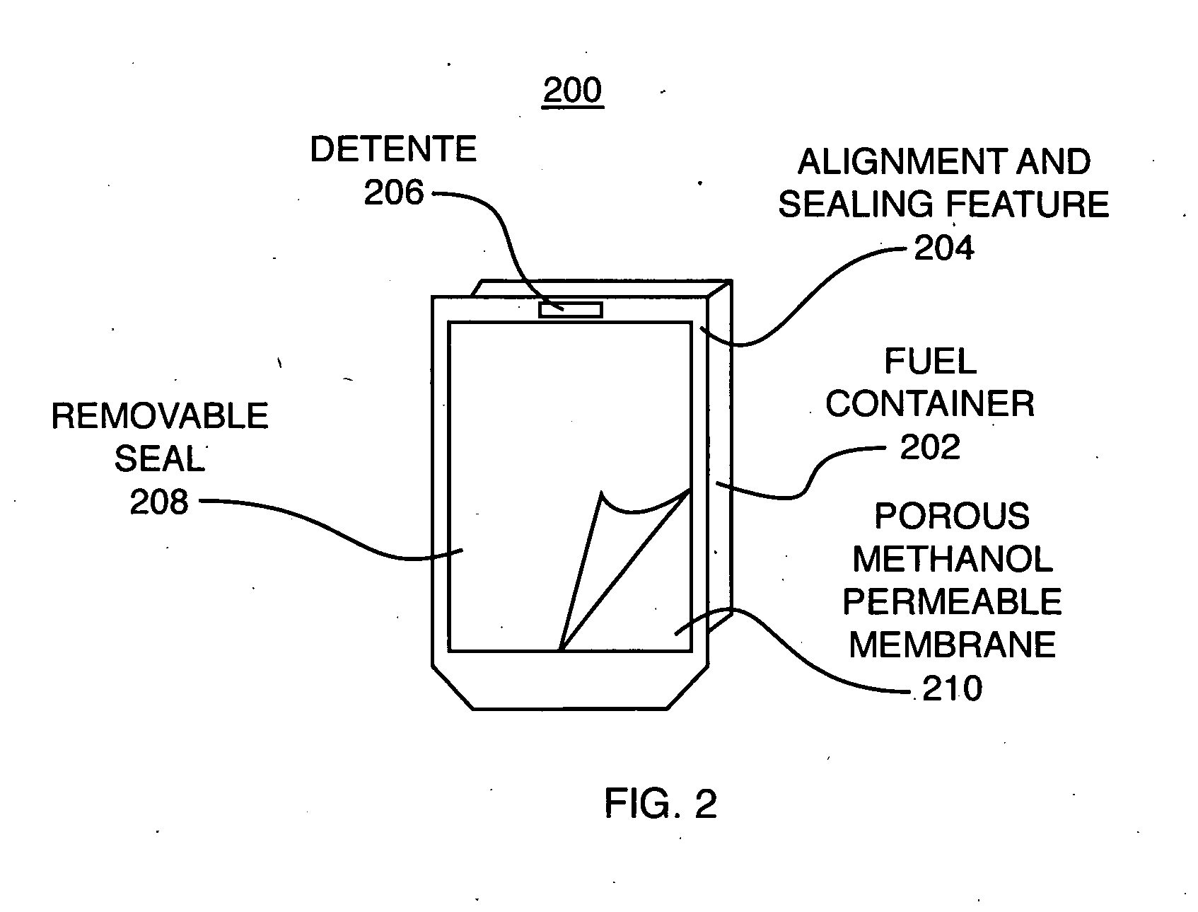
[0027] The fuel substance combined with the thickening substance, and additives, if any, together form the unique “viscous fuel” of the present invention, which provides benefits over previous fuels, including performance enhancements and desirable physical characteristics. The viscous fuel may then be placed into a fuel reservoir of a fuel cartridge constructed in accordance with the present invention. Disposed within the fuel reservoir is a reticulated material, generally a felt or a foam. The addition of this reticulated material, either alone or in combination with the viscous fuel, assists the prevention of undesired flow of the fuel, and minimization of undesired leakages. The mat

Problems solved by technology

However, because fuel processing is expensive and generally requires expensive components, which occupy significant volume, reformer-based systems are presently limited to comparatively large, high power applications.
In addition, it could lead to the generation of undesirable anode products such as formaldehyde.
However, such pervaporation membranes may need to be specially engineered, which can be costly.
In addition, some such membranes, though useful for delivering the vaporous fuel, can, degrade in the presence of the methanol fuel, compromising the delivery of fuel.
This typically requires additional components that consume power, increasing the parasitic losses within the system, and adding additional complexity, expense, and volume.
Additional recirculation subsystems, including pumps, valves and other fluid management equipment and components may increase the size of the overall fuel cell system, and in some cases may increase it significantly.
However, even though such expansion bladders and optional force-applying elements may be desirable

Method used


Image

  • Fuel container with reticulated material
  • Fuel container with reticulated material
  • Fuel container with reticulated material

Examples


Embodiment Construction

Fuel Formulation and Properties

[0044] In accordance with the present invention, a viscous fuel is formulated from a fuel substance, thickening substances, and additives, if any, for use in a direct oxidation fuel cell. A portion of the composition of the fuel substance is substantially neat methanol. A thickening substance is added, which imparts thickening, thereby increasing viscosity, while still maintaining the fuel as a freely flowing liquid. In accordance with one implementation of the invention, the thickening substance is a chemical sold commercially under the trademark Carbopol® EZ-3 helogy modifier, which is a hydrophobically modified cross-linked polyacrylate polymer sold by Noveon, Inc. of 9911 Brecksville Road, Cleveland, Ohio 44141-3247, USA. It is desirable to use a formulation that is non-hazardous.

[0045] Depending on the precise formulation of the thickener, it may be necessary or desirable to include a pH balancing substance. In accordance with one aspect of the...


PUM


Abstract

A fuel reservoir having a reticulated material, generally a felt or a foam, disposed therein is provided. The addition of this reticulated material, either alone or in combination with a viscous fuel, assists the prevention of undesired flow of the fuel, the minimization of undesired leakages, and assists in orientation independence and uniform distribution of the fuel in the reservoir. The reticulated material enables the use of a viscous liquid fuel that has fuel diffusion rates and fuel utilization characteristics that approach those of neat liquid methanol. The material also helps create a greater surface area for evaporation, thus allowing a highly concentrated, vaporous fuel substance to be delivered to an associated fuel cell.

Description

CROSS REFERENCES TO RELATED APPLICATIONS [0001] The present application is a continuation-in-part of commonly assigned copending U.S. patent application Ser. No. 10 / 688,433, filed on Oct. 17, 2003, by Becerra et al. for a FUEL SUBSTANCE AND ASSOCIATED CARTRIDGE FOR FUEL CELL, which is incorporated herein by reference. This application is related to commonly-assigned United States Patent Application No. (Atty.-Docket 107044-0040P2), filed on even date herewith, by Ren et al., for a FUEL FORMULATION FOR DIRECT METHANOL FUEL CELL, which is incorporated herein by reference.BACKGROUND OF THE INVENTION [0002] 1. Field of the Invention [0003] This invention relates generally to direct oxidation fuel cells, and more particularly, to fuel storage for such fuel cells. [0004] 2. Background Information [0005] Fuel cells are devices in which electrochemical reactions are used to generate electricity. A variety of materials may be suited for use as a fuel depending upon the materials chosen for t...

Claims


Application Information

Patent Timeline
IPC IPC(8): C10L7/04H01M8/04H01M8/10
CPCC10L7/04H01M8/04082Y02E60/523H01M8/1009H01M8/1011H01M8/04208Y02E60/50Y10T137/86276
Inventor MANNING, MICHAEL P.MODI, ASHISH K.REN, XIAOMINGGULESERIAN, LENA A.
Owner MTI MICROFUEL CELLS
Why Eureka
Try Eureka