Floating brake rotor assembly with non-load bearing pins

a floating, brake rotor technology, applied in the direction of brake discs, braking systems, friction linings, etc., can solve the problems of increasing the likelihood of thermal induced distortion hub and pin deformation, and localized wear and deformation of the brake rotor, so as to facilitate assembly and replacement of the components

Active Publication Date: 2005-04-21
GEHRS JEFFREY W
View PDF4 Cites 34 Cited by
  • Summary
  • Abstract
  • Description
  • Claims
  • Application Information

AI Technical Summary

Benefits of technology

[0013] The floating brake rotor assembly with non-load bearing pins includes a brake rotor and hub that are coplanar and are interconnected by pin and spring assemblies such that the pins do not bear rotational torque being transferred between the rotor and the hub. The rotor has tooth-like protruding members along its inner edge that mate with recessess along the outer edge of the hub. When aligned, each protruding member and corresponding recess form an aperture through which a pin is positioned, and allows for transfer of rotational torque without applying load force to the pin. This coplanar configuration with pin apertures formed between the rotor and hub allows for ease in assembling and replacing the components.

Problems solved by technology

Consequently, several known problems are associated with each manner.
First, because load thrust transfer must occur across a relatively small surface area, localized wear and deformation of the brake rotor, hub and pins occur frequently.
Third, thermal transfer capacity from the brake rotor to the hub is constrained, thereby lessening heat dissipation and increasing the likelihood of thermal induced distortion of the brake rotor.
As discussed above, this configuration results in the entire load transfer between the rotor and hub being transferred via the pins and further results in the aforementioned problems.
However, this configuration also results in the entire load transfer between the rotor and hub being transferred via the pins.
Additionally, Bunker uses a combined pin and leaf spring, which complicates assembly and replacement of the rotor.
However, due to lateral torque forces, the non-coplanar configuration of the rotor and hub is more prone to produce warping and excessive wear.
This configuration requires precise placement of the spring groove, pin shaft, and recessed areas, and thus complicates manufacture, assembly and replacement of the components.

Method used


Image

  • Floating brake rotor assembly with non-load bearing pins
  • Floating brake rotor assembly with non-load bearing pins
  • Floating brake rotor assembly with non-load bearing pins

Examples


Embodiment Construction

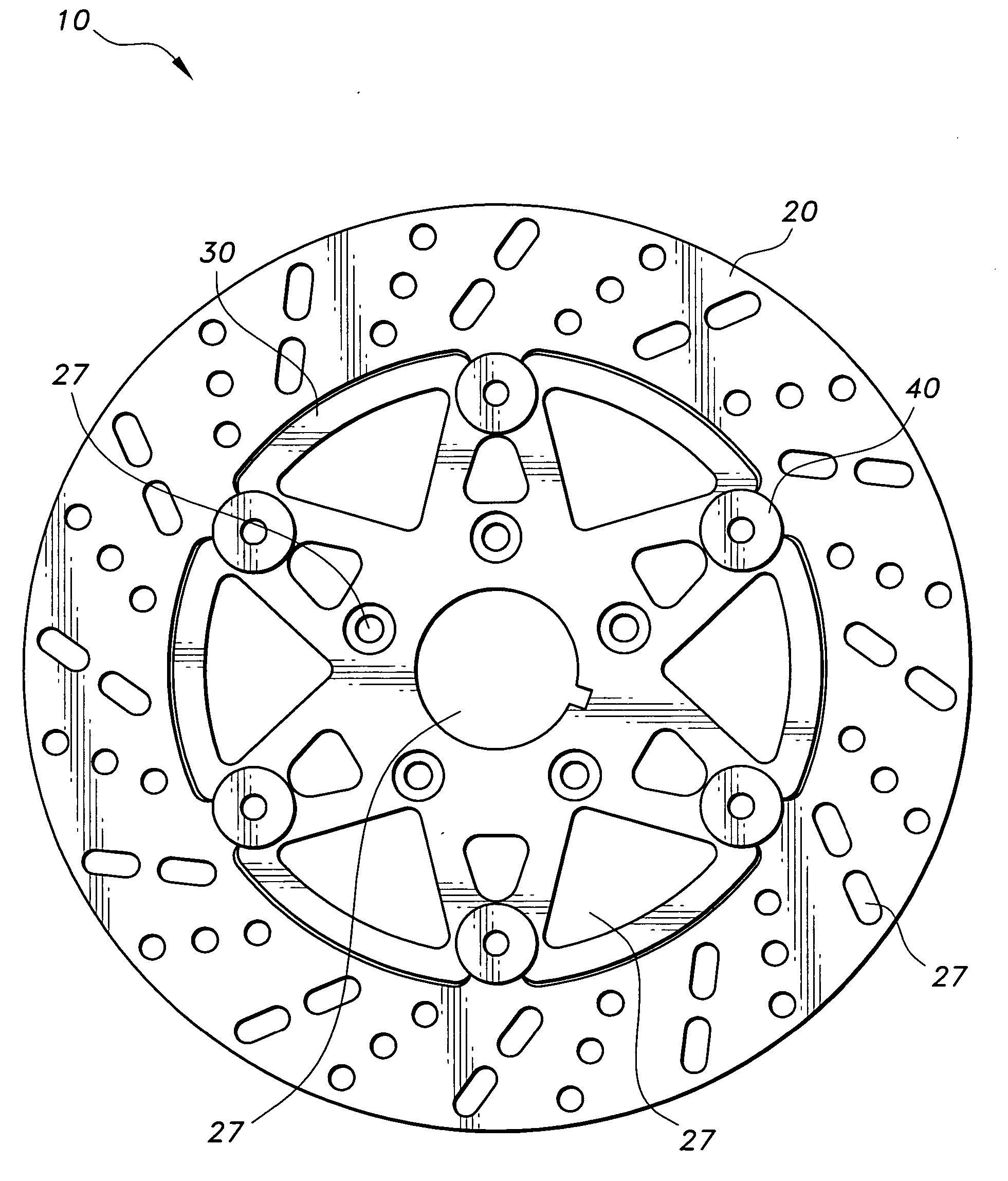
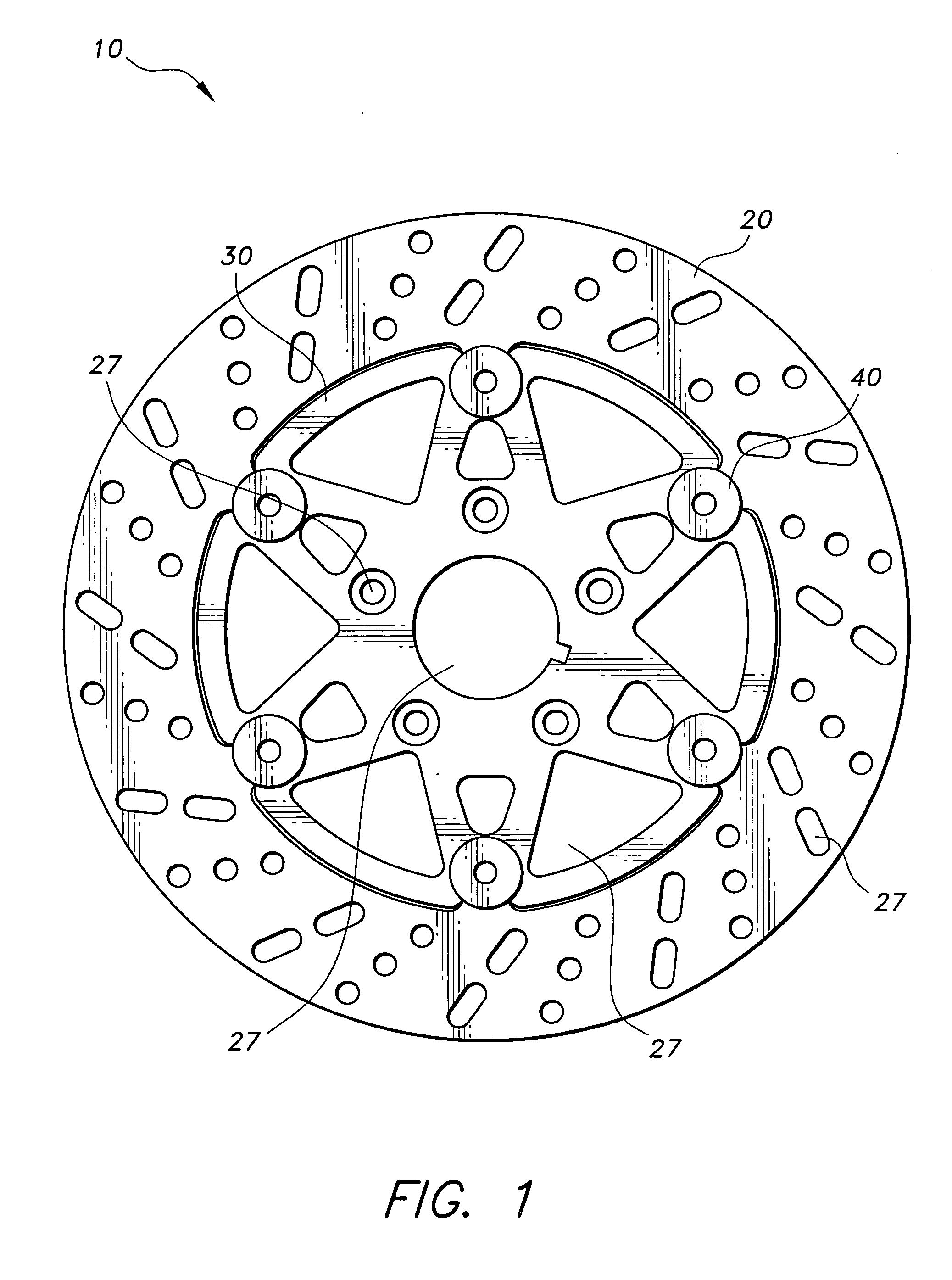
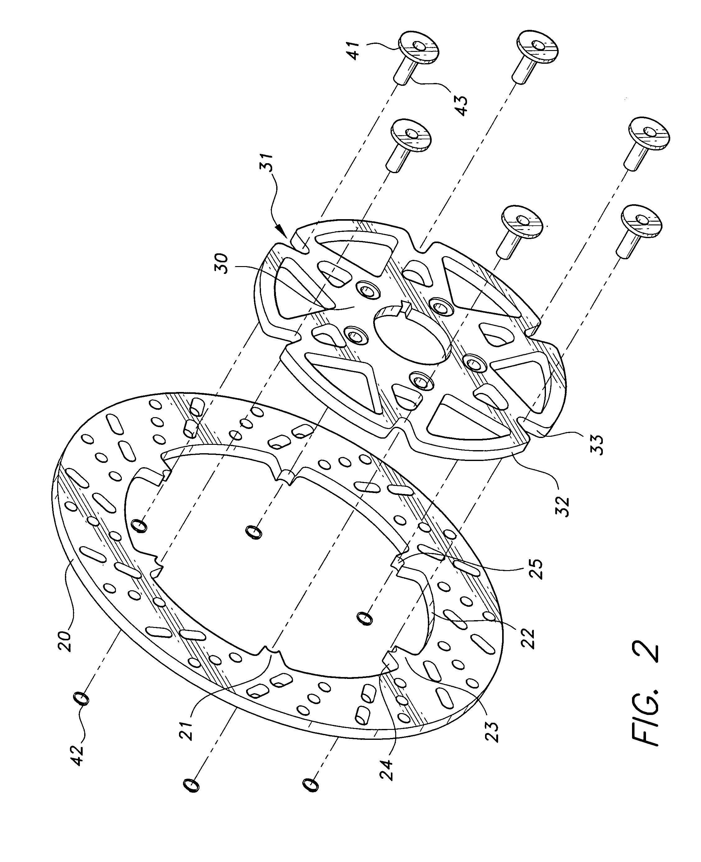
[0030] The present invention is a floating brake rotor assembly with non-load bearing pins designated generally as 10 in the drawings. As shown in FIGS. 1 and 2, the invention includes a brake rotor 20 that is secured to a hub 30 by six pin and spring assemblies 40.

[0031] The brake rotor 20 is an annular disk with two opposing flat sides or faces, and six protruding members 21 or teeth extending from its 20 inner circumferential edge 22. Each protruding member 21 has two lateral faces 23 and two radially extending bearing faces 24. Each lateral face 23 is flush with the lateral faces of the brake rotor 20 and each radially extending bearing face 24 is perpendicular to the lateral faces of the brake rotor 20. The two radially extending bearing faces 24 taper toward each other from the proximal end to the distal end 25 of each protruding member 21, i.e., from the rim towards the center of the rotor 20. From a lateral perspective, the distal end 25 of each protruding member 21 is conc...


PUM


Abstract

The floating brake rotor assembly with non-load bearing pins includes a brake rotor and hub that are coplanar and are interconnected by pin and spring assemblies such that the pins do not bear rotational torque being transferred between the brake rotor and hub. The rotor has tooth-like protruding members along its inner edge that mate with recessess along the outer edge of the hub. When aligned, each protruding member and corresponding recess forms an aperture through which a pin is positioned, and allows for transfer of rotational torque without applying load force to the pin.

Description

BACKGROUND OF THE INVENTION [0001] 1. Field of the Invention [0002] The present invention relates to disc brake assemblies, and more particularly to a floating brake rotor assembly in which the connecting pins are not subject to torque forces transferred from the brake rotor to the hub. [0003] 2. Description of the Related Art [0004] Various designs for floating brake rotor assemblies have been proposed. Examples of such designs are provided by U.S. Pat. No. 4,848,521, issued Jul. 18, 1989 to Z. Izumine; U.S. Pat. No. 5,520,269, issued May 28, 1996 to S. Yamamoto et al.; U.S. Pat. No. 5,921,633, issued Jul. 13, 1999 to P. Neibling et al.; U.S. Pat. No. 6,267,210, issued Jul. 31, 2001 to D. L. Burgoon et al.; U.S. Pat. No. 6,305,510, issued Oct. 23, 2001 to K. J. Bunker; and U.S. Pat. No. 6,374,956, issued Apr. 23, 2002 to E. Naeumann et al. [0005] In general, a floating brake rotor assembly is comprised of a brake rotor and a hub. The brake rotor is annular with two flat sides that ...

Claims


Application Information

Patent Timeline
Patent Type & Authority Applications(United States)
IPC IPC(8): F16D65/00F16D65/12F16D69/00
CPCF16D65/12F16D2065/1316F16D2069/004F16D2065/1392F16D2065/1396F16D2065/1368
Inventor GEHRS, JEFFREY W.
Owner GEHRS JEFFREY W
Why Eureka
Try Eureka