Electro-kinetic air transporter and conditioner devices with a mesh collector electrode

Inactive Publication Date: 2005-04-21
THE SHARPER IMAGE
View PDF99 Cites 24 Cited by
  • Summary
  • Abstract
  • Description
  • Claims
  • Application Information

AI Technical Summary

Benefits of technology

[0012] In accordance with embodiments of the present invention, the outer hollow mesh electrode includes an electrically conductive mesh covered by an insulating dielectric mate

Problems solved by technology

However, the extent that the voltage difference can be increased is limited because arcing may eventually occur between the collector electrodes 122 and the driver electrodes 232.
Such arc

Method used


Image

  • Electro-kinetic air transporter and conditioner devices with a mesh collector electrode
  • Electro-kinetic air transporter and conditioner devices with a mesh collector electrode
  • Electro-kinetic air transporter and conditioner devices with a mesh collector electrode

Examples


Embodiment Construction

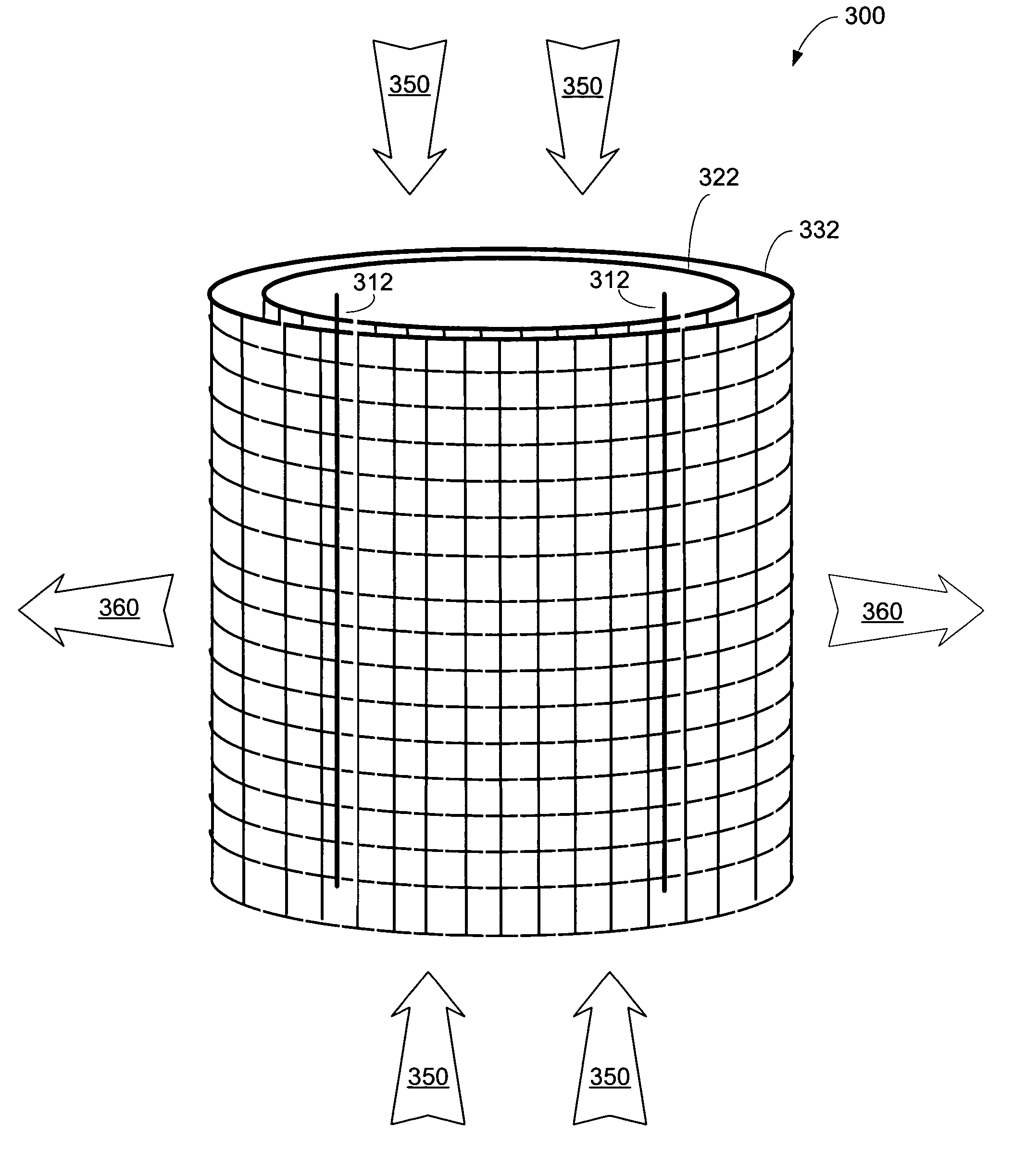
[0025]FIG. 3A illustrates a perspective view of an electro-kinetic conditioner system 300, according to an embodiment of the present invention. The system 300 is shown as including a pair of emitter electrode(s) 312, surrounded by a cylindrical mesh collector electrode 322. In accordance with an embodiment of the present invention, an outer cylindrical mesh electrode 332 surrounds the cylindrical mesh collector electrode 322.

[0026]FIG. 3B only shows the outlines of the cylindrical electrodes 322 and 332, and thus provides a simplified perspective view of the system 300 shown in FIG. 3A. In this embodiment, the emitter electrode(s) 312 are shown as being grounded, while the cylindrical mesh collector electrode 322 is shown as being connected to a negative terminal of a high voltage source 340. The outer cylindrical mesh electrode 332 is also shown to be grounded. FIG. 3C shows a top view of the embodiment of FIGS. 3A and 3B.

[0027] In accordance with an embodiment of the present inv...


PUM


Abstract

Embodiments of the present invention are related to electro-kinetic air transporter-conditioner systems and methods. An electro-kinetic air conditioner device includes an inner hollow cylindrical mesh electrode having a first radius and an outer hollow cylindrical mesh electrode having a second radius that is larger than the first radius. The second hollow cylindrical mesh electrode surrounds the first hollow cylindrical mesh electrode. At least one emitter electrode is located within and generally parallel to the first hollow cylindrical electrode. A voltage source provides a high voltage potential difference between each emitter electrode and the inner hollow cylindrical mesh electrode. The outer hollow mesh electrode is preferably grounded, as well as insulated.

Description

CROSS REFERENCE TO RELATED APPLICATIONS [0001] The present application is related to the following application and patent, each of which is incorporated herein by reference: U.S. patent application Ser. No. 60 / 500,437, filed Sep. 5,2003, entitled “Electro-Kinetic Air Transporter and Conditioner Devices with Insulated Driver Electrodes” and; U.S. Pat. No. 6,176,177, entitled “Electro-Kinetic Air Transporter Conditioner.”FIELD OF THE INVENTION [0002] The present invention relates generally to devices that electro-kinetically transport and / or condition air. BACKGROUND OF THE INVENTION [0003] It is known in the art to produce an airflow using electro-kinetic techniques, by which electrical power is converted into a flow of air without mechanically moving components. One such system was described in U.S. Pat. No. 4,789,801 to Lee (1988), depicted herein in simplified form as FIGS. 1A and 1B. System 100 includes a first array 110 of emitter electrodes 112 that are spaced-apart from a seco...

Claims


Application Information

Patent Timeline
IPC IPC(8): A61L9/015B01JB01J19/08B01J19/12F24F3/16
CPCA61L9/22B03C3/06B03C3/09B03C3/49F24F2003/1685B03C2201/10B03C2201/14F24F3/166B03C2201/04F24F8/192F24F8/40Y02A50/20
Inventor BOTVINNIK, IGOR Y.
Owner THE SHARPER IMAGE
Why Eureka
Try Eureka